JVC SR-W5U Instruction Manual - Page 8
Controls And Connectors
 |
View all JVC SR-W5U manuals
Add to My Manuals
Save this manual to your list of manuals |
Page 8 highlights
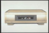
2 CONTROLS AND CONNECTORS Front Panel 1 2 34 5 6 7 PHONES VOLUME REC LEVEL IR REMOTE MANUAL AUTO MIN MAX REMOTE PAUSE INPUT LINE4 OFF ON EDIT(HD REC) NR(W-VHS PLAY) ON OFF VIDEO L- AUDIO -R Y/C TIMING R C L 8 TRACKING AUTO 1 [S-VIDEO/VIDEO/AUDIO INPUT 4] connectors Connect to the S-VIDEO/VIDEO/AUDIO OUTPUT connectors on the playback deck or camcorder with the S-VIDEO/VIDEO/AUDIO cable when this machine is used as a recording unit for editing. If the sound is monaural, plug it to the AUDIO L connector. Identical audio sound will be recorded for left and right channels. [REMOTE PAUSE] connector When editing with a JVC camcorder, connect the mini-plug cord to this connector. 2 [PHONES] connector Accepts the mini plug type headphone. [VOLUME] adjust knob Adjust the sound level of headphone connected to the PHONES connector. 3 [REC LEVEL] switch MANUAL: Set to this position when adjusting the Hi-Fi recording level and the volume balance between left and right audio channels manually. AUTO : Normally set to this position. 4 [IR REMOTE] switch OFF: Set to this position when not operating with a wireless remote control unit. ON : Normally set to this position. [EDIT(HD REC)/NR(W-VHS PLAY)] switch When using W-VHS tapes, adjust the picture to the desired tone. ON : • Set to this position when noise is noticeable during playback of HD/SD recorded tapes. • Set to this position when recording from Hi- Vision video cameras and from professional equipment. 8 OFF : • Normally set to this position during playback. • Set to this position when recording from another W-VHS VCR. [Y/C TIMING] switch Adjusts the horizontal color phase. R : Set to this position when the color phase shifts toward the left. C : Normally set to this position. L : Set to this position when the color phase shifts toward the right. * This function is not effective while playing back a tape recorded in the HD mode. 5 Tape loading slot door 6 Video unit display window Displays the operational state of the recorder, counter and so on. 7 Infrared beam receiving window 8 [TRACKING -/+] button Suppresses the disturbances appearing on the picture when a tape recorded on another machine is played back (or put on slow motion playback). [AUTO] button Turns on and off the auto tracking facility.
-
 1
1 -
2
-
 3
3 -
 4
4 -
 5
5 -
 6
6 -
 7
7 -
 8
8 -
 9
9 -
 10
10 -
 11
11 -
 12
12 -
 13
13 -
14
-
15
-
16
-
17
-
18
-
19
-
20
-
21
-
22
-
23
-
24
-
25
-
26
-
27
-
28
-
29
-
30
-
31
-
32
-
33
-
34
-
35
-
36
 |
 |
