JVC TK-C1460U Instruction Manual - Page 12
Connection/installation, Rm-p2580 System
 |
View all JVC TK-C1460U manuals
Add to My Manuals
Save this manual to your list of manuals |
Page 12 highlights
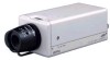
CONNECTION/INSTALLATION RM-P2580 System Ⅲ System with up to 8 cameras Av Pk L ALC L Camera 1 MACHINE ID:1 (Menu screen) RX TERM: OFF (switch) Av Pk L H ALC LEVEL Camera TK-C1460 Camera TK-C1460 Control signal cable Video signal cable Power cable AC24V or DC12V Camera 2 MACHINE ID:2 (Menu screen) RX TERM: OFF (switch) Camera TK-C1460 AC24V or DC12V Av Pk L H ALC LEVEL Camera 8 MACHINE ID:8 (Menu screen) RX TERM: ON (switch) AC24V or DC12V MONITOR C•AM SW Time lapse VCR OUT REC STOP/EJECT REC CHECK VIDEO CASSETTE RECORDER SR-L910 OPERATE PAUSE/ REVERSE STILL PLAY REW FF COUNT/ CLOCK MENU SHIFT/TRACKING RESET /CANCEL TIME MODE TIMER REC SET/V.LOCK AL/PL RESET VIDEO IN OPE. LOCK TO CAMERA CAMERA SW COM Remote Control Unit RM-P2580 POWER TO CAMERA RX RX TX TX COM DATA I / O UNIT CAMERA COM 9/1 10/2 11/3 12/4 13/5 14/6 15/7 16/8 COM AUTO ALARM COM SW COM ON OFF AC INPUT TO CAMERA RX+ RX- TX+ TX- VIDEO INPUT DATA I / O UNIT CAMERA COM 1 2 3 4 5 6 7 8 COM 9/1 10/2 11/3 12/4 13/5 14/6 15/7 16/8 COM AUTO ALARM COM SW COM VIDEO INPUT 1 2 3 4 5 6 7 ON VIDEO OUTPUT 12 34 56 78 ON 1 2 3 4 5 6 7 VIDEO OUTPUT SERIAL-1 MONITOR OUTPUT 2 SERIAL-2 MONITOR MONITOR OUTPUT OUTPUT 8 MONITOR MONITOR MONITOR OUTPUT OUTPUT 1 2 O8 UTPUT 1 MONITOR When controlling with any system except the RM-P2580, execute proper settings using switches and menu screens according to the systems used. (੬ Page 14) MEMO • When operating a system using the RM-P2580, several cameras (up to 16) can be connected and used on one control signal cable. Consequently, an incorrect switch setting on just a single camera will cause the entire system to work incorrectly. • Confirm switch settings on the screen as follows. q Confirm that the image from the camera to be checked MONITOR screen (example showing camera ID as "05") is displayed on the monitor. w Turn OFF and then ON the AC 24 V power to the camera to be checked. e The camera begins the initial operation and charac- ters similar to those shown in the illustration on the right appear on the monitor screen. r Confirm that "DUPLEX" and "ID-□□" are displayed and that the ID number is the correct number (the PROT OCO L : DUP L E X I D - 0 5 number should be the same as the number of the VIDEO INPUT terminal to which the camera is con- nected on the rear panel of the RM-P2580). t If wrong, set the camera ID again. E-12 "DUPLEX" should The number shown in the be displayed. □□ part of ID-□□ should be correct.
-
 1
1 -
2
-
3
-
4
-
5
-
6
-
 7
7 -
 8
8 -
 9
9 -
 10
10 -
 11
11 -
 12
12 -
 13
13 -
 14
14 -
 15
15 -
 16
16 -
 17
17 -
18
-
19
-
20
-
21
-
22
-
23
-
24
-
25
-
26
-
27
-
28
-
29
-
30
-
31
-
32
-
33
-
34
-
35
-
36
-
37
-
38
-
39
-
40
-
41
-
42
-
43
-
44
-
45
-
46
-
47
-
48
-
49
-
50
-
51
-
52
-
53
-
54
-
55
-
56
-
57
-
58
-
59
-
60
-
61
-
62
-
63
-
64
-
65
-
66
-
67
-
68
-
69
-
70
-
71
-
72
-
73
-
74
-
75
-
76
-
77
-
78
-
79
-
80
-
81
-
82
-
83
-
84
-
85
-
86
-
87
-
88
-
89
-
90
-
91
-
92
-
93
-
94
-
95
-
96
-
97
-
98
-
99
-
100
-
101
-
102
-
103
-
104
-
105
-
106
-
107
-
108
-
109
-
110
-
111
-
112
-
113
-
114
-
115
-
116
-
117
-
118
-
119
-
120
-
121
-
122
-
123
-
124
-
125
-
126
-
127
-
128
-
129
-
130
-
131
-
132
-
133
-
134
-
135
-
136
-
137
-
138
-
139
-
140
-
141
-
142
-
143
-
144
-
145
-
146
-
147
-
148
-
149
-
150
-
151
-
152
-
153
-
154
-
155
-
156
-
157
-
158
-
159
-
160
-
161
-
162
-
163
-
164
-
165
-
166
-
167
-
168
-
169
-
170
-
171
-
172
-
173
-
174
-
175
-
176
-
177
-
178
-
179
-
180
-
181
-
182
-
183
-
184
-
185
-
186
-
187
-
188
-
189
-
190
-
191
-
192
-
193
-
194
-
195
-
196
-
197
-
198
-
199
-
200
-
201
-
202
-
203
-
204
-
205
-
206
-
207
-
208
-
209
-
210
-
211
-
212
 |
 |
