JVC TK-C9300UA Instruction Manual - Page 10
Mounting the Camera Continued, Fall Prevention, Connection/Installation
 |
View all JVC TK-C9300UA manuals
Add to My Manuals
Save this manual to your list of manuals |
Page 10 highlights
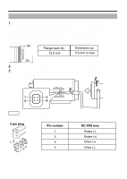
Connection/Installation Mounting the Camera (Continued) Fall Prevention m v Special attention is required when installing the camera to the wall or ceiling. You should not engage in the installation work yourself. Ask a professional to do the job, because injuries and accidents may occur if the camera falls. v When installing the camera on a fixer, pan/tilt unit and the like, make sure to install it firmly using a rotation-preventive hole to prevent fall. v To prevent fall, connect the camera to a section with sufficient strength (ceiling slab or channel) using a fall prevention wire. v Pay attention to the length, strength, routing and material (insulation properties) of the fall prevention wire used. v Use the screw (M3 x 6 mm) on the back of the camera for the installation of the fall prevention wire. Do not use a screw that is longer than 6 mm as it may damage the internal parts. . 6mm 6 mm OFF D/N AUTO ON BLC OFF CRT LCD ON AES OFF MONITOR TYPE CLASS(U2TOYNPLEY) ISOONLALYTE(EDTPYOPWEE) R AUX GND SEE INSTRUCTMIOANNUAL VIDEO OUT FOCUS ADJUST SET MENU DC12V 2 AC24V 1 Fall Prevention Wire M3 x 6 mm 2 mm . Note When mounting the camera to the ceiling, ensure to wear safety glasses to protect the eye from any falling objects. 10
-
 1
1 -
2
-
3
-
4
-
 5
5 -
 6
6 -
 7
7 -
 8
8 -
 9
9 -
 10
10 -
 11
11 -
 12
12 -
 13
13 -
 14
14 -
 15
15 -
16
 |
 |
