Jenn-Air JGC3115GS Instruction Sheet - Page 5
Important
 |
View all Jenn-Air JGC3115GS manuals
Add to My Manuals
Save this manual to your list of manuals |
Page 5 highlights
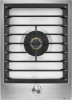
6. Remove all burner caps and burner bases. Be sure to keep the cap and base for each burner together. This will assure A that the cap and base are reinstalled on the proper burner. B Single Burner A. Cap B. Spreader C. Electrode A B A B C Double Burner A. Cap B. Spreader C. Electrode C Dual Flame Burner A. Igniter electrode B. Orifice holder C. Orifice spud IMPORTANT: Place Natural gas orifice spuds in plastic parts bag for future use and keep with package containing literature. 8. Replace burner bases and burner caps. IMPORTANT: Be sure that the electrode aligns with the notch or hole in the burner base. The igniter electrode is ceramic and could break during installation of the burner base. A C D Dual Flame Burner A. Inner cap B. Outer cap C. Spreader D. Electrode 7. To convert burners: ■■ Insert 7.0 mm nut driver down onto the gas orifice spud (C) and remove by turning it counterclockwise and lifting out. ■■ Set gas orifice spud aside. ■■ Replace with correct Propane gas orifice spud. See the Propane Gas Orifice Spud Chart. AB B C A D B C A. Burner cap B. Electrode C. Burner base 9. Open shut-off valve in the gas supply line. The valve is open when the handle is parallel to the gas pipe. 10. Once you have completed converting all of the cooktop burners, test the cooktop for leaks by brushing on an approved noncorrosive leak-detection solution. If bubbles appear, a leak is indicated. Correct any leaks found. C Standard Burner A. Igniter electrode B. Orifice holder C. Orifice spud Double Burner A. Igniter electrode B. Orifice holder C. Orifice spud D. Orifice simmer 11. Plug in cooktop or reconnect power. 12. Adjust valve according to the "Low Flame Height Adjustment" section. 5
-
 1
1 -
 2
2 -
 3
3 -
 4
4 -
 5
5 -
 6
6 -
 7
7 -
 8
8 -
 9
9 -
 10
10 -
 11
11 -
12
-
13
-
14
-
15
-
16
-
17
-
18
-
19
-
20
 |
 |
