Jensen CD6112 Instruction Manual - Page 8
Wiring Diagram
 |
UPC - 043258303790
View all Jensen CD6112 manuals
Add to My Manuals
Save this manual to your list of manuals |
Page 8 highlights
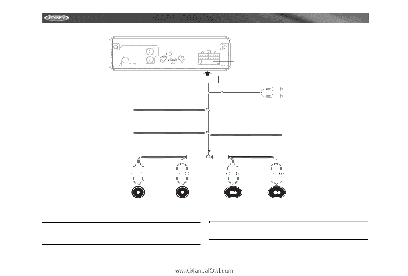
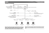
WIRING DIAGRAM CD6112 Antenna Connect the antenna plug from the existing antenna cable (some vehicles require an adaptor). Fuse (15 amp fast blow ATO) R (Red) L (White) Aux-in Ground Connect to ground terminal or clean, unpainted part of chassis. Memory/Battery Connect to battery or 12 volt power source that is always live. The radio will not work if this wire is not connected. White/Black Stripe Black Yellow White Gray/Black Stripe Rear Line out Gray Blue Red FRONT SP REAR SP Gray Green/Black Stripe Green Purple/Black Stripe R (Red) L (White) Power Antenna Connect to power antenna or amplifier. If not used, tape bare end of wire. Accessory/Ignition Connect to existing radio wire or radio fuse. Purple Left Speaker (Front) Right Speaker (Front) Left Speaker (Rear) Right Speaker (Rear) NOTE: The amplifier in this radio is only designed for use with four speakers. Never combine (bridge) outputs for use with two speakers. Never ground negative speaker leads to chassis ground. Failure to wire exactly as shown may cause electrical damage to the radio. NOTE: Only connect speakers rated in the load impedance of 4 ohms. Speakers with a load impedance less than 4 ohms could damage the unit. 4
-
 1
1 -
2
-
 3
3 -
 4
4 -
 5
5 -
 6
6 -
 7
7 -
 8
8 -
 9
9 -
 10
10 -
 11
11 -
 12
12 -
 13
13 -
14
-
15
-
16
-
17
-
18
-
19
-
20
-
21
-
22
-
23
-
24
 |
 |