Jensen JN102 Installation Guide - Page 10
Troubleshooting - remote
 |
UPC - 044476029639
View all Jensen JN102 manuals
Add to My Manuals
Save this manual to your list of manuals |
Page 10 highlights
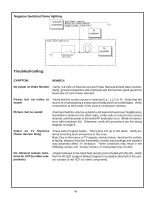
Negative Switched Dome lighting To 12 pin Red / black - Lamp on connector Black / red - Lamp common Purple / brown - Lamp Auto To constant Factory Dome light circuit Factory Door ajar switch or Body To constant Troubleshooting: SYMPTOM: REMEDY: No power at Video Monitor -Verify +12 VDC on Red wire at 2 pin Power Harness behind video monitor. Verify ground connection with continuity test from known good ground to black wire at 2 pin Power Harness Power but no video or -Verify that the correct source is selected (i.e.: 1,2,3 or 4). Verify that the sound source is on and playing a known good media (such as a videotape). Verify connections at both ends of the source component harness. Picture, but no sound -Push and hold the volume up button until sound is heard over headphones. If problem is limited to the dash radio, verify radio is tuned to the correct channel, and that power to the wired RF modulator is on. (Refer to instructions with modulator kit). Otherwise, verify all connections per the wiring diagram on page 6. Static on TV Stations (Tuner Version Only) -Press Auto Program button. Then press CH up or CH down. Verify antenna mounting and connections to the tuner. Note: Due to the nature of TV signals, vehicle motion, direction the vehicle is facing, distance from the transmitter, nearby surroundings and weather may adversely affect TV reception. These conditions may result in the following: picture roll, "snowy" picture, or momentary loss of color. No Infrared remote func- -Check batteries in the hand held remote (not included with this kit). Verify tions for VCP (or other com- that the IR LED ( page 6 Wiring Diagram) is properly attached to the sen- ponents) sor window of the VCP (or other component). -8-
-
 1
1 -
2
-
3
-
4
-
 5
5 -
 6
6 -
 7
7 -
 8
8 -
 9
9 -
 10
10 -
 11
11
 |
 |
