Jensen VM9312HD Operation Manual - Page 6
What's in the Box, Optional Equipment, Tools and Supplies, Disconnecting the Battery, Pre- - remote control
 |
UPC - 043258304179
View all Jensen VM9312HD manuals
Add to My Manuals
Save this manual to your list of manuals |
Page 6 highlights
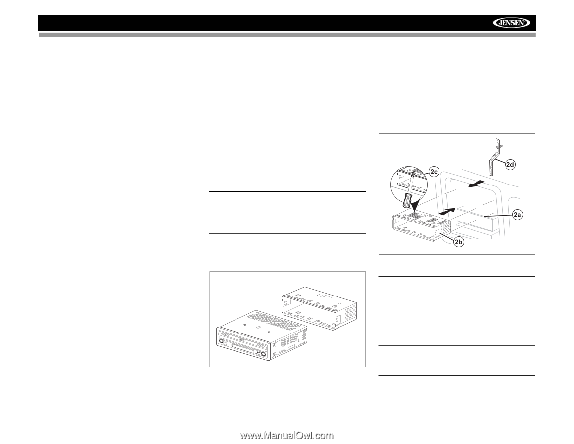
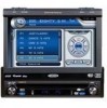
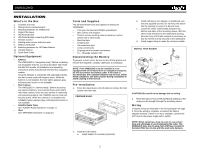
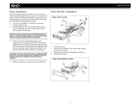
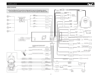
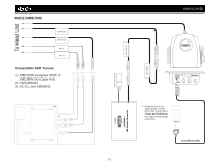
VM9312HD INSTALLATION What's in the Box 1. Cosmetic trim ring 2. Wiring harness power/speaker 3. Mounting hardware for VM9312HD 4. Single DIN sleeve 5. HD Radio Module 6. HD Radio Module connecting DIN cable 7. Remote Control 8. Parking brake sensor extension wire 9. Media Link Module 10. Mounting hardware for HD Radio Module 11. Owners Manual 12. Quick Start Guide Optional Equipment • NAV101 The VM9312HD is "navigation ready." Before accessing any navigation features, you must purchase and install the NAV101 module. All installation and operating instructions will be included with the NAV101 navigation module. Once the NAV101 is connected and operating properly, the NAV source mode will become active. While the NAV101 is not installed, the NAV option appears gray, indicating the function is not available. • Rear Camera The VM9312HD is "camera ready." Before accessing any camera features, you must purchase and install a rear video camera. Once the rear camera is connected and operating properly, the CAMERA source mode will become active. While the camera is not installed, the CAMERA option appears gray, indicating the function is not available. • Satellite Radio Tuner See "Satellite Radio Operation" on page 17. • iPod See "MP3/WMA Operation" on page 23. Tools and Supplies You will need these tools and supplies to install your VM9312HD: • Torx type, flat-head and Philips screwdrivers • Wire cutters and strippers • Tools to remove existing radio (screwdriver, socket wrench set or other tools) • Electrical tape • Crimping tool • Volt meter/test light • Crimp connections • 18 gauge wire for power connections • 16 - 18 gauge speaker wire Disconnecting the Battery To prevent a short circuit, be sure to turn off the ignition and remove the negative (-) battery cable prior to installation. NOTE: If the VM9312HD is to be installed in a car equipped with an on-board drive or navigation computer, do not disconnect the battery cable. If the cable is disconnected, the computer memory may be lost. Under these conditions, use extra caution during installation to avoid causing a short circuit. Pre-installation 1. Press the metal levers on both sides to remove the halfsleeve from the radio. PREPARE RADIO BAND AS/PS PRELOSS/DAXUDIO VM9312 SRC DISP OPEN EJECT MUTE 2. Install the half-sleeve. a. Install adapter if necessary (optional). b. Install half-sleeve into adapter or dashboard (use only the supplied screws). Do not force the sleeve into the opening or cause it to bend or bow. c. Locate the series of bend-tabs along the top, bottom and sides of the mounting sleeve. With the sleeve fully inserted into the dashboard opening, bend as many of the tabs outward as necessary so that the sleeve is firmly secured to the dashboard. d. Install support strap to make the unit more stable. INSTALL HALF SLEEVE CAUTION! Be careful not to damage the car wiring. 3. Place the radio in front of the dashboard opening so the wiring can be brought through the mounting sleeve. Wiring Complete wiring as illustrated in the wiring diagram on page 3. Once the wiring is complete, reconnect the battery negative terminal. If there is no ACC available, connect the ACC lead to the power supply with a switch. NOTE: When replacing a fuse, be sure to use correct type and amperage to avoid damaging the radio. The VM9312HD uses one 15 amp mini-ATM fuse, located in the black filter box in-line with the main wire harness. 2
-
 1
1 -
 2
2 -
 3
3 -
 4
4 -
 5
5 -
 6
6 -
 7
7 -
 8
8 -
 9
9 -
 10
10 -
 11
11 -
 12
12 -
13
-
14
-
15
-
16
-
17
-
18
-
19
-
20
-
21
-
22
-
23
-
24
-
25
-
26
-
27
-
28
-
29
-
30
-
31
-
32
-
33
-
34
-
35
-
36
-
37
-
38
 |
 |