Kenmore 3050 Use and Care Guide - Page 8
Setting, Surface, Controls
 |
View all Kenmore 3050 manuals
Add to My Manuals
Save this manual to your list of manuals |
Page 8 highlights
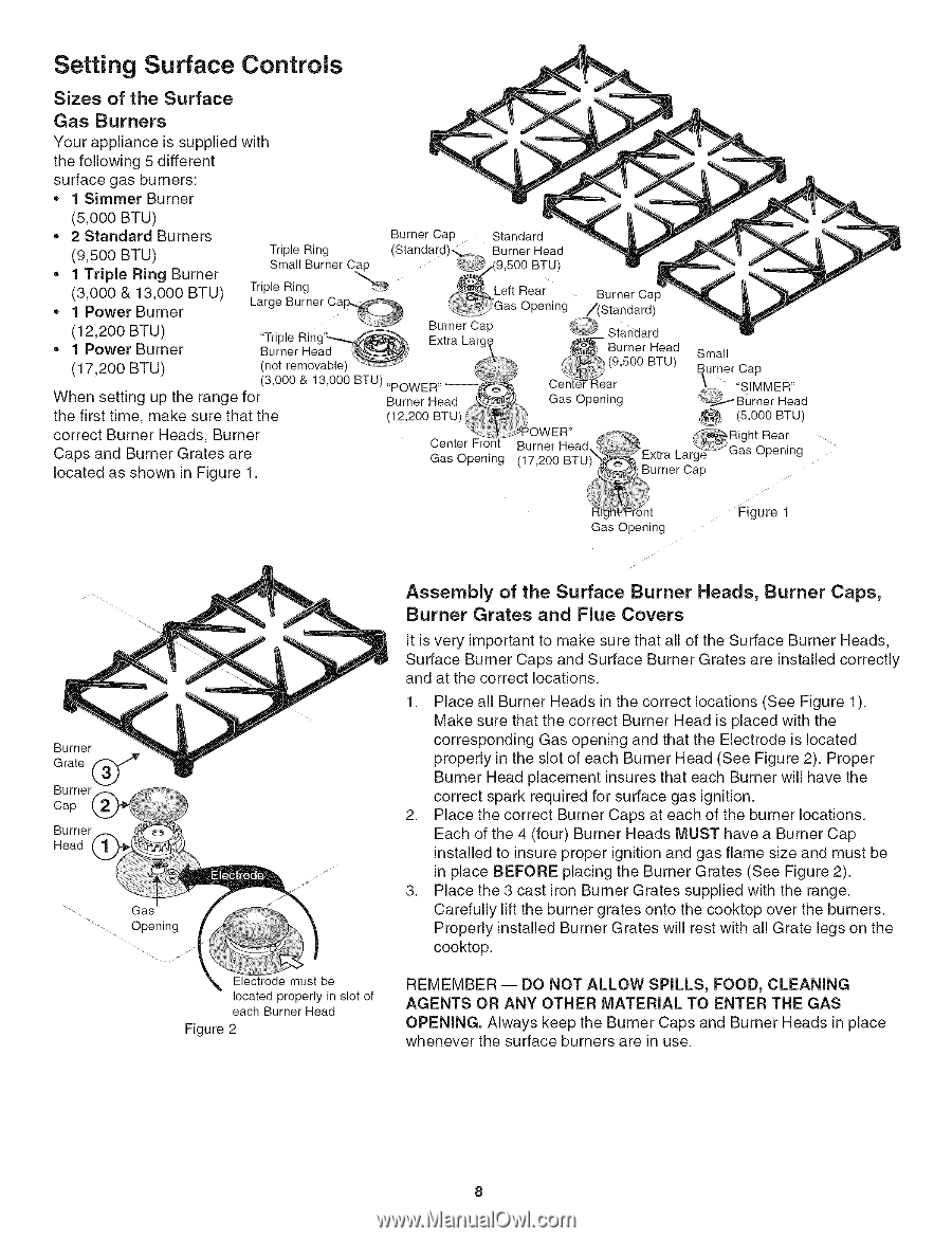
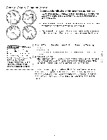
Setting Surface Controls Sizes of the Surface Gas Burners Your appliance is supplied with the following 5 different surface gas burners: • 1 Simmer Burner (5,000 BTU) = 2 Standard Burners (9,500 BTU) • 1 Triple Ring Burner (3,000 & 13,000 BTU) • 1 Power Burner Triple Ring Small Burner C_ Triple Ring _ Large Burner Ca_ Burner Cap Standard (Standard).,.. .... Burner Head __ _Left .(9,500 BTU) Rear Gas Openin ,_ Burner Can t ..... _r (12,200 BTU) • 1 Power Burner (17,200 BTU) not removab e (3,000 & 13,000 BTU),,POWER,,_ When setting up the range for the first time, make sure that the correct Burner Heads, Burner Caps and Burner Grates are B(1u2r,n2e0r0 HBeTaUd_)I Center Front GasOpening located as shown in Figure 1. Cent (9,500 BTeUa)d SBmuranlel r Cap ar _.,_, "SIMMER" Gas Opening OWER" _""_*_ __ B(5u.0rn0e0r BHTeUad Right Rear Burner Head _c _Gas O_enin (17.200BTU - _'_ Extra Large- _" g urner CaD t Gas Opentng Figure 1 Burner Grate _ Burner Cap Burner Head Gas upentng Electrode must be located properly in slot of each Burner Head Figure 2 Assembly of the Surface Burner Heads, Burner Caps, Burner Grates and Flue Covers It is very important to make sure that all of the Surface Burner Heads, Surface Burner Caps and Surface Burner Grates are installed correctly and at the correct locations. 1. Place all Burner Heads in the correct locations (See Figure 1). Make sure that the correct Burner Head is placed with the corresponding Gas opening and that the Electrode is located properly in the slot of each Burner Head (See Figure 2). Proper Burner Head placement insures that each Burner will have the correct spark required for surface gas ignition. 2. Place the correct Burner Caps at each of the burner locations. Each of the 4 (four) Burner Heads MUST have a Burner Cap installed to insure proper ignition and gas flame size and must be in place BEFORE placing the Burner Grates (See Figure 2). 3. Place the 3 cast iron Burner Grates supplied with the range. Carefully lift the burner grates onto the cooktop over the burners. Properly installed Burner Grates will rest with all Grate legs on the cooktop. REMEMBER -- DO NOT ALLOW SPILLS, FOOD, CLEANING AGENTS OR ANY OTHER MATERIAL TO ENTER THE GAS OPENING. Always keep the Burner Caps and Burner Heads in place whenever the surface burners are in use.
-
 1
1 -
2
-
 3
3 -
 4
4 -
 5
5 -
 6
6 -
 7
7 -
 8
8 -
 9
9 -
 10
10 -
 11
11 -
 12
12 -
 13
13 -
14
-
15
-
16
 |
 |