Kenmore 3050 Installation Instructions - Page 1
Kenmore 3050 - Pro 36 in. Gas Slide-In Cooktop Manual
 |
View all Kenmore 3050 manuals
Add to My Manuals
Save this manual to your list of manuals |
Page 1 highlights
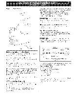
INSTALLATION AND SERVICE MUST BE PERFORMED BY A QUAUHED INSTALLER. IMPORTANT: SAVE FOR LOCAL ELECTRICAL INSPECTOR'S USE. READ AND SAVE THESE INSTRUCTIONS FOR FUTURE REFERENCE. [f the information in this manual is not followed exactly, a fire or explosion may result causing property damage, personal injury or death. FOR YOUR SAFETY: -- Do not store or use gasoline or other flammabJe appliance. -- WHAT TO DO tF YOU SMELL GAS: vapors and liquids in the vMnity of this or any other * Do not try to light any appliance. Do not touch any e[ectrka[ switch; do not use any phone in your building, Immediately call your gas supplier from a neighbor's phone. Follow the gas supp[ier's instructions. ,, ff you cannot reach your gas supplier, ca[[ the fire department. -- Installation and servke must be performed by a qualified installer, servke agency or the gas supplier. For Standard Installation: Gas Cooktop Dimensions /A * 30" (76.2 cm) rain. for unprotected cabinet and 24" (61 cm) rain. for cabinet with protected bottom surface. Gas Cooktop Cutout Dimensions 2"(5.1 cm) Dia. Opening to route -- power cabFe F G Do not slide unit into cabinet cutout, Protruding screws on the bottom of ur it may damage the bottom front finish. X4" (!0.2 cm x 10.2 cm) opening to route gas supply. 71/4 (18.4 cm) Figure 1 **Note: D & E are critical to the proper installation of the cooktop. D reflects the finished dimension. Due to the variation in countertop materials, it is recommended to first undercut this dimension, and then adjust it upon installation of the cooktop. All dimensions are stated in inches and (cm). NOTE: Wiring diagrams for this cooktop are enclosed in this booklet 318201459 (0407) Rev A English - pages 1o10 Espar_ol - Diginas 11-19 Wiring Diagram page - 20
-
 1
1 -
 2
2 -
 3
3 -
 4
4 -
 5
5 -
 6
6 -
 7
7 -
8
-
9
-
10
-
11
-
12
-
13
-
14
-
15
-
16
-
17
-
18
-
19
-
20
 |
 |