Kenmore 3050 Installation Instructions - Page 5
I0.2 cm - appliances
 |
View all Kenmore 3050 manuals
Add to My Manuals
Save this manual to your list of manuals |
Page 5 highlights
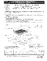
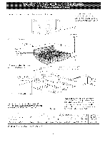
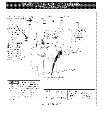
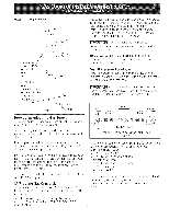
Wall Outlet Location _ 4 ,,_ (I0.2 cm) ..... 5" 0 (12.7 cm) Recommended area for 120V grounded outlet on rear wall. NOTE: If an outlet is not available, have one installed by a qualified technician. , 'm _ _CENTRE _LINE OF UNIT | | i 16 ii (40.6 cm) 1 I , "_ GCENTR E LLINE Figure 4 OFUNIT Provide an Adequate Gas Supply This cooktop is designed to operate on natural gas at 4" (10.2 cm) of manifold pressure only. A pressure regulator is connected in series with the manifold on the cooktop and must remain in series with the supply line. For proper operation, the maximum inlet pressure to the regulator must be no more than 14" (35.6 cm) of water column (W.C.) pressure. For checking the regulator, tile inlet pressure must be at least 1 "(2.5 cm) (or 2.5 kPa) greater than the regulator manifold pressure setting. The regulator is set for 4" (10.2 cm) of manifold pressure, the inlet pressure must be at least 5" (12.7 cm). Tile gas supply line to the range should be 1/2" (1.3 cm) or 3/4" (1.g cm) pipe. LP/Propane Gas Conversion This appliance can be used with Natural gas or LP/ Propane gas. It is shipped from the factory for use with natural gas. A kit for converting to LP gas is supplied with your cooktop. The kit is marked "FOR LP/PROPANEGAS CONVERSION". The conversion must be performed by a qualified service technician in accordan(e with the kit instructions and all local codes and requirements. Failure to follow instructions could result in serious injury or property damage. Tile qualified agency performing this work assumes responsibility for the conversion. Failure to make the appropriate conversion can result in serious personal injury and property damage. Important: Remove all packing material and literature from cooktop before connecting gas and electrical supply to cooktop. Install Pressure Regulator Install the pressure regulator with the arrow on the regulator pointing up toward the unit in a position where you can reach the access cap. Do not make the connection too tight. The regulator is die cast. Overtightening may crack the regulator resulting in a gas leak and possible fire or explosion. Manual Shutoff Valve FUare Union GAS FLOW _ Flare Union Pressu_-e Reg_Bator , /A" ...... ....... OntN _-_ Off F[exibme Connector All connections must be wrench4ightened Figure 5 Assemble the flexible connector from the gas supply pipe to the pressure regulator in tile following order: 1. manual shutoff valve 2. 1/2" (1.3 cm) nipple 3. 1/2" (! .3 cm) flare union adapter 4. flexible connector 5. 1/2" (1.3 cm) flare union adapter 6. 1/2" (1.3 cm) nipple 7. pressure regulator Use pipe-joint compound made for use with Natural and LP/Propane gas to seal all gas connections. If flexible connectors are used, be certain connectors are not kinked.
-
 1
1 -
 2
2 -
 3
3 -
 4
4 -
 5
5 -
 6
6 -
 7
7 -
 8
8 -
 9
9 -
 10
10 -
 11
11 -
12
-
13
-
14
-
15
-
16
-
17
-
18
-
19
-
20
 |
 |
