Kenmore 32656 Owners Manual - Page 11
Converting, the Lower, Element, cont'd
 |
View all Kenmore 32656 manuals
Add to My Manuals
Save this manual to your list of manuals |
Page 11 highlights
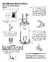
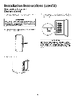
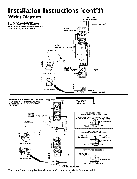
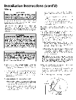
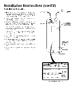
Installation Instructions (cont'd) Converting the Lower Element (cont'd) 2. The convertible element is located behind the lower access panel of the water heater. Remove the two screws securing the access panel, and remove panel. 5. Remove the screws from terminal 2 of the element, and move the looped end of the wire aside. 3. Remove the insulation block and pad. 6. The buss bar is labeled 5500 W. Place the buss bar over terminals 2 and 3 with the 5500 W visible. Install the extra screw provided into terminal 3. 4. Lower Element: Lift out the tab as shown to unclip the terminal cover from the thermostat. The terminal cover can be removed from the thermostat. Lift out tab to until term hal cover from _hermostat, JAeKETli \ TERHINALCOVER, CLIPPED TO THER- MOSTAT AT THIS \ POINT \ PLASTIC TABS ON BOTH SIDES OF TERHINAL COVER HOLD IT iN PLACE. THERHOSTAT /BRACKET _TANK LOWER THERHOSTAT ELEHENT 7. The wire removed from terminal 2 has a looped end. It must remain looped and now be placed (as shown) on top of the buss bar, over the opening of terminal 2, and secured using the remaining screw. 8. Tighten terminals 2 and 3 to ensure proper electrical connection. &WARNING Failure to tighten terminal screws can cause a fire which can result in DEATH, SERIOUS BODILY INJURY, OR PROPERTY DAMAGE. 11
-
 1
1 -
2
-
3
-
4
-
5
-
 6
6 -
 7
7 -
 8
8 -
 9
9 -
 10
10 -
 11
11 -
 12
12 -
 13
13 -
 14
14 -
 15
15 -
 16
16 -
17
-
18
-
19
-
20
-
21
-
22
-
23
-
24
-
25
-
26
-
27
-
28
-
29
-
30
-
31
-
32
 |
 |
