Kenmore 32986 Owners Manual - Page 10
FitT&Pvalve
 |
View all Kenmore 32986 manuals
Add to My Manuals
Save this manual to your list of manuals |
Page 10 highlights
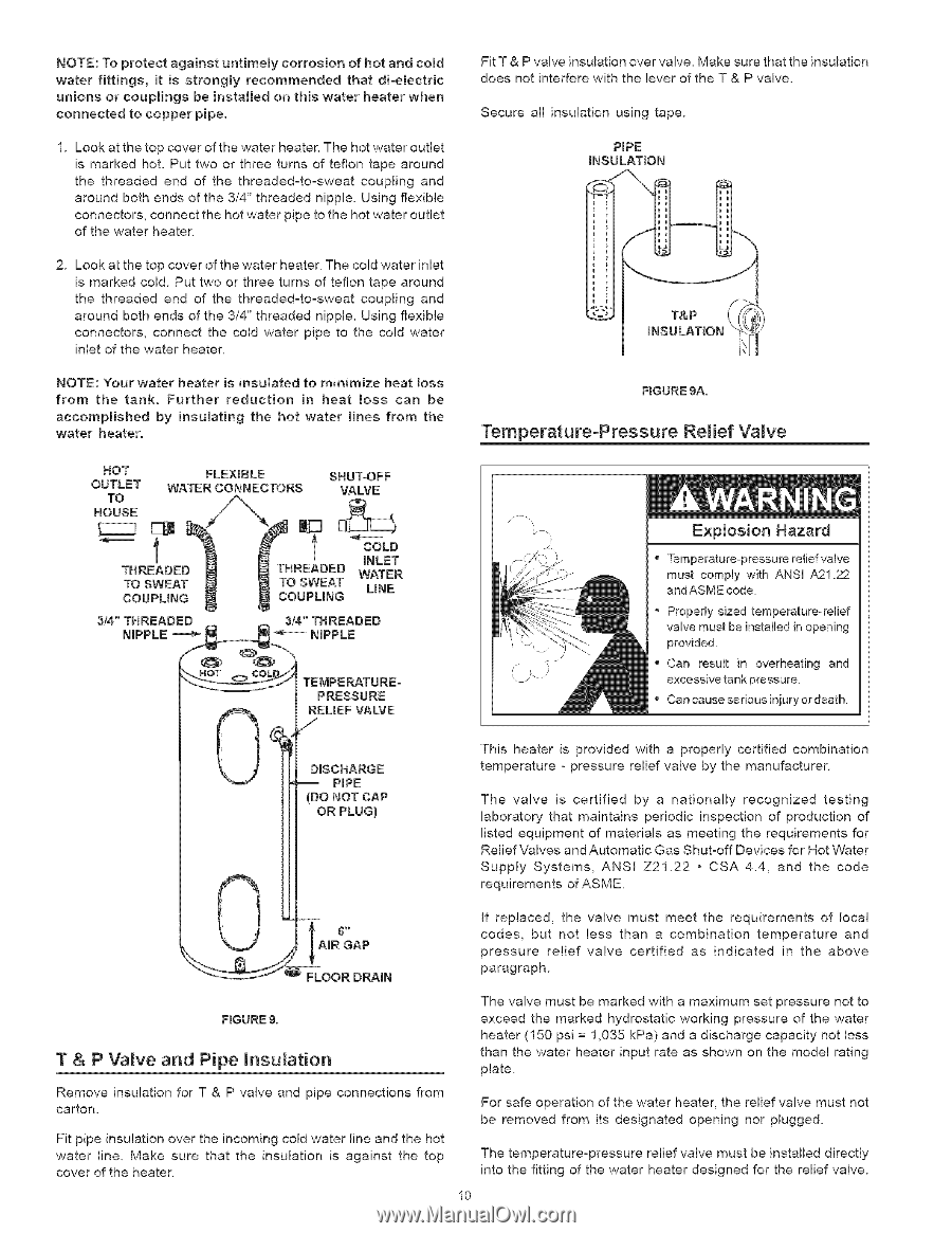
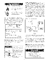
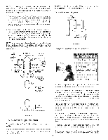
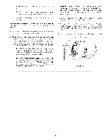
NOTET:oprotecatgainsutntimelycorrosionofhotandcored FitT&Pvalveinsulatioonvevr alveM. akesurethatheinsulation waterfittings,it is stronglyrecommendethdatdioemectric doesnotinterferweiththeleveor ftheT&Pvalve. unionsorcouplingsbeinstalledor}thiswaterheatewr hen connectetdocoppepr ipe. Secureall insulatiounsingtape. 1.Lookatthetopcoveor fthewatehr eateTr.hehotwateor utlet is markehdot.Puttwoorthreeturnsofteflontapearound thethreadeedndof thethreaded-to-swceoautplingand aroundbothendsofthe3/4"threadendippleU. singflexible connectocrso,nnecthtehotwatepr ipetothehotwateor utlet ofthewatehr eater. PiPE iNSULATION 2. Lookatthetopcoveor fthewatehr eateTr.hecoldwateirnlet ismarkecdoldP. uttwoorthreeturnsofteflontapearound thethreadeedndof thethreaded-to-swceoautplingand aroundbothends of the 3/4" threaded nipple. Using flexible connectors, connect the cold water pipe to the cold water inlet of the water heater. i iNSULATION \i\_J NOTE: Your water heater is insulated to minimize heat loss from the tank. Further reduction in heat Boss can be accomplished water heater. by insu[ating the hot water lines from the FIGURE gA. Temperature-Pressure Relief Valve HOT OUTLET TO FLEXIBLE WATER CONNECTORS SHUT-OFF VALVE HOUSE [_ l THREADED TO SWEAT COUPLING THREADED TO SWEAT COUPLING CINOLLEDT WATER UNE PRESSURE REUEF VALVE /" DISCHARGE -- PIPE (DO NOT CAP OR PLUG} Explosion Hazard , Temperature-pressure relief valve must comply with ANSI A21.22 and ASME code. " Properly sized temperature-relief valve must be installed in opening provided. , Can result in overheating and excessive tank pressure " Can cause serious iniury or death. This heater is provided with a properly certified combination temperature - pressure relief valve by the manufacturer. The valve is certified by a nationally recognized testing laboratory that maintains periodic inspection of production of listed equipment of materials as meeting the requirements for Relief Valves and Automatic Gas Shut-off Devices for Hot Water Supply Systems, ANSI Z21.22 • CSA 4.4, and the code requirements of ASME. If replaced, the valve must meet the requirements of local codes, but not less than a combination temperature and pressure relief valve certified as indicated in the above paragraph. FIGUREg. T & P Valve and Pipe insulation The valve must be marked with a maximum set pressure not to exceed the marked hydrostatic working pressure of the water heater (150 psi = 1,035 kPa) and a discharge capacity not less than the water heater input rate as shown on the model rating plate. Remove insulation for T & P valve and pipe connections from carton. Fit pipe insulation over the incoming cold water line and the hot water line. Make sure that the insulation is against the top cover of the heater. For safe operation of the water heater, the relief valve must not be removed from its designated opening nor plugged. The temperature-pressure relief valve must be installed directly into the fitting of the water heater designed for the relief valve. 10
-
 1
1 -
2
-
3
-
4
-
 5
5 -
 6
6 -
 7
7 -
 8
8 -
 9
9 -
 10
10 -
 11
11 -
 12
12 -
 13
13 -
 14
14 -
 15
15 -
16
-
17
-
18
-
19
-
20
-
21
-
22
-
23
-
24
-
25
-
26
-
27
-
28
-
29
-
30
-
31
-
32
 |
 |