Kenmore 32986 Owners Manual - Page 15
ratedat20amperes
 |
View all Kenmore 32986 manuals
Add to My Manuals
Save this manual to your list of manuals |
Page 15 highlights
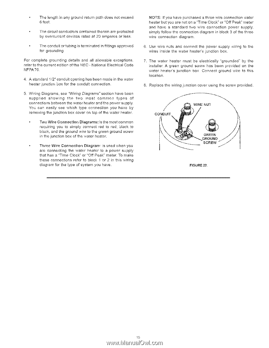
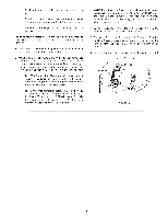
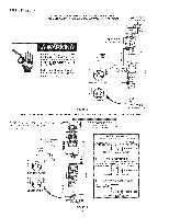
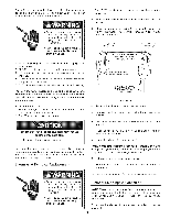
Thelengthinanygroundreturnpathdoesnotexceed 6feet, Thecircuictonductocrsontainethdereianreprotected byovercurrednet vicersatedat20ampereosrless, NOTE: If you have purchased a three wire connection water heater but you are not on a 'Time Clock" or 'Off Peak" meter and have a standard two wire connection power supply, simply follow the connection diagram in block 3 of the three wire connection diagram, Theconduoitrtubingisterminateindfittingsapproved 6, Use wire nuts and connect the power supply wiring to the forgrounding, wires inside the water heater's junction box, Forcompletgeroundindgetailsandallallowableexceptions, refetrothecurrenetditionoftheNEC- NationaEllectricCalode NFPA70, The water heater must be electrically "grounded" by the installer. A green ground screw has been provided on the water heater's unction box, Connect ground wire to this 4, A standar1d/2"conduoitpeninhgasbeenmadeinthewater location. heatejrunctionboxfortheconducitonnection, 8, Replace the wiring junction cover using the screw provided, 5, WiringDiagramsse, e"Wiring Diagrams" section have been supplied showing the two most common types of connections between the water heater and the power supply. You can easily see which type connection you have by removing the junction box cover on top of the water heater, CONDU_T Two Wire Connection Diagrams: is the most common requiring you to simply connect red to red, black to black, and the ground wire to the green ground screw in the junction box of the water heater. Three Wire Connection Diagram: is used when you are connecting the water heater to a power supply that has a "Time Clock" or "Off Peak" meter, To make these connections refer to block 1 or 2 in this wiring diagram for the type of system you have, GREEN GROUND SCREW FIGURE 23. 15
-
 1
1 -
2
-
3
-
4
-
5
-
6
-
7
-
8
-
9
-
 10
10 -
 11
11 -
 12
12 -
 13
13 -
 14
14 -
 15
15 -
 16
16 -
 17
17 -
 18
18 -
 19
19 -
 20
20 -
21
-
22
-
23
-
24
-
25
-
26
-
27
-
28
-
29
-
30
-
31
-
32
 |
 |