Kenwood KDC-BT92SD User Manual - Page 36
Accessories/ Installation Procedure, Connecting Wires to Terminals, For Good Reception - protect
 |
View all Kenwood KDC-BT92SD manuals
Add to My Manuals
Save this manual to your list of manuals |
Page 36 highlights
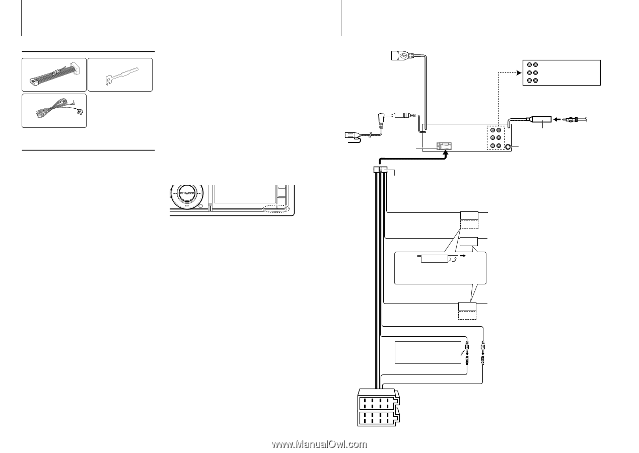
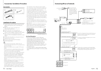
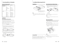
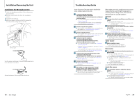
Accessories/ Installation Procedure Accessories 1 2 ..........1 3 3 m ..........1 ..........2 Installation Procedure 1 To prevent short circuits, remove the key from the ignition and disconnect the - terminal of the battery. 2 Make the proper input and output wire connections for each unit. 3 Connect the wire on the wiring harness. 4 Take Connector B on the wiring harness and connect it to the speaker connector in your vehicle. 5 Take Connector A on the wiring harness and connect it to the external power connector on your vehicle. 6 Connect the wiring harness connector to the unit. 7 Install the unit in your car. 8 Reconnect the - terminal of the battery. 9 Press the reset button. ¤ • Mounting and wiring this product requires skills and experience. For safety's sake, leave the mounting and wiring work to professionals. • Make sure to ground the unit to a negative 12V DC power supply. • Do not install the unit in a spot exposed to direct sunlight or excessive heat or humidity. Also avoid places with too much dust or the possibility of water splashing. • Do not use your own screws. Use only the screws provided. If you use the wrong screws, you could damage the unit. • If the power is not turned ON ("Protect" is displayed), the speaker wire may have a short-circuit or touched the chassis of the vehicle and the protection function may have been activated. Therefore, the speaker wire should be checked. • Make sure that all wire connections are securely made by inserting jacks until they lock completely. • If your vehicle's ignition does not have an ACC position, or if the ignition wire is connected to a power source with constant voltage such as a battery wire, the power will not be linked with the ignition (i.e., it will not turn on and off along with the ignition). If you want to link the unit's power 71 | KDC-BT92SD with the ignition, connect the ignition wire to a power source that can be turned on and off with the ignition key. • Use a commercially available conversion connector if the connector does not fit in the vehicle connector. • Insulate unconnected wires with vinyl tape or other similar material. To prevent a short circuit, do not remove the caps on the ends of the unconnected wires or the terminals. • If the console has a lid, make sure to install the unit so that the faceplate will not hit the lid when closing and opening. • If the fuse blows, first make sure the wires aren't touching to cause a short circuit, then replace the old fuse with one with the same rating. • Connect the speaker wires correctly to the terminals to which they correspond. The unit may be damaged or fail to work if you share the - wires or ground them to any metal part in the car. • After the unit is installed, check whether the brake lamps, blinkers, wipers, etc. on the car are working properly. • Mount the unit so that the mounting angle is 30° or less. • Reception may drop if there are metal objects near the Bluetooth antenna. Bluetooth antenna unit For Good Reception To assure good reception, note the following: • Communicate with the cell-phone within the line- of-sight distance of 10 m (30 ft). The communication range becomes shorter depending on the surrounding environment. The communication range also becomes shorter when there is an obstacle between this unit and the cell-phone. The above maximum communication range (10 m) is not always assured. • A broadcast station or walkie-talkie located nearby can interfere with communication due to too strong signal. Connecting Wires to Terminals To USB device USB connector (0.8m) ⁄ Do not remove the cap when you do not use the USB cable. The connector will cause the unit to malfunction if it gets in touch with any metallic part of the vehicle. Microphone input Microphone (Accessory 3) RL Fuse (10A) R L Rear output Front output Sub Woofer output Antenna Cord FM/AM antenna input (JASO) AUX input (Stereo) Use the mini-plug which is stereo type and does not have any resistance. Wiring harness (Accessory 1) Light Blue/Yellow (Steering remote control wire) Brown (Mute control wire) REMOTE CONT STEERING WHEEL REMOTE INPUT MUTE To use the steering wheel remote control feature, you need to an exclusive remote adapter (not supplied) matches your car is required. To connect the Kenwood navigation system, consult your navigation manual. If no connections are made, do not let the wire come out from the tab. Blue/White (Power control/ Antenna control wire) Yellow (Battery wire) Red (Ignition wire) P.CONT ANT.CONT ⁄ See next page Connect either to the power control terminal when using the optional power amplifier, or to the antenna control terminal in the vehicle. (Max. 300mA, 12V) Red (A-7 Pin) Yellow (A-4 Pin) 864 2 75 31 8 64 2 75 31 Connector A Connector B English | 72
-
 1
1 -
2
-
3
-
4
-
5
-
6
-
7
-
8
-
9
-
10
-
11
-
12
-
13
-
14
-
15
-
16
-
17
-
18
-
19
-
20
-
21
-
22
-
23
-
24
-
25
-
26
-
27
-
28
-
29
-
30
-
 31
31 -
 32
32 -
 33
33 -
 34
34 -
 35
35 -
 36
36 -
 37
37 -
 38
38 -
 39
39 -
 40
40 -
 41
41
 |
 |