Kenwood KDC-BT92SD User Manual - Page 37
Installation/Removing the Unit, Connector Function Guide, WARNING, Connecting the ISO Connector - wiring
 |
View all Kenwood KDC-BT92SD manuals
Add to My Manuals
Save this manual to your list of manuals |
Page 37 highlights
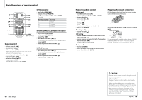
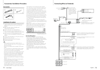
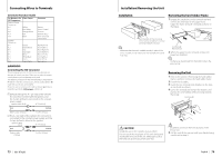
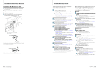
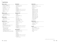
Connecting Wires to Terminals Connector Function Guide Pin Numbers for Cable Colour ISO Connectors External Power Connector A-4 Yellow A-5 Blue/White A-6 Orange/White A-7 Red A-8 Black Speaker Connector B-1 B-2 B-3 B-4 B-5 B-6 B-7 B-8 Purple Purple/Black Gray Gray/Black White White/Black Green Green/Black Functions Battery Power Control Dimmer Ignition (ACC) Earth (Ground) Connection Rear Right (+) Rear Right (-) Front Right (+) Front Right (-) Front Left (+) Front Left (-) Rear Left (+) Rear Left (-) 2WARNING Connecting the ISO Connector The pin arrangement for the ISO connectors depends on the type of vehicle you drive. Make sure to make the proper connections to prevent damage to the unit. The default connection for the wiring harness is described in 1 below. If the ISO connector pins are set as described in 2, make the connection as illustrated. Please be sure to reconnect the cable as shown 2 below to install this unit to the Volkswagen vehicles etc. 1(Default setting) The A-7 pin (red) of the vehicle's ISO connector is linked with the ignition, and the A-4 pin (yellow) is connected to the constant power supply. Ignition cable (Red) A-7 Pin (Red) Unit Vehicle Battery cable (Yellow) A-4 Pin (Yellow) 2The A-7 pin (red) of the vehicle's ISO connector is connected to the constant power supply, and the A-4 pin (yellow) is linked to the ignition. Ignition cable (Red) A-7 Pin (Red) Unit Vehicle Battery cable (Yellow) A-4 Pin (Yellow) 73 | KDC-BT92SD Installation/Removing the Unit Installation Removing the hard rubber frame 1 Engage the catch pins on the removal tool and remove the two locks on the upper level. Upper the frame and pull it forward as shown in the figure. Bend the tabs of the mounting sleeve with a screwdriver or similar utensil and attach it in place. ⁄ • Make sure that the unit is installed securely in place. If the unit is unstable, it may malfunction (for example, the sound may skip). Lock Catch Accessory2 Removal tool 2 When the upper level is removed, remove the lower two locations. ⁄ • The frame can be removed from the bottom side in the same manner. Removing the Unit 1 Refer to the section and then remove the hard rubber frame. 2 Detach the faceplate. 3 Insert the two removal tools deeply into the slots on each side, as shown. 4 Lower the removal tool toward the bottom, and pull out the unit halfway while pressing towards the inside. Accessory2 ¤ CAUTION Install this unit in the console of your vehicle. Do not touch the metal part of this unit during and shortly after the use of the unit. Metal part such as the heat sink and enclosure become hot. ¤ • Be careful to avoid injury from the catch pins on the removal tool. 5 Pull the unit all the way out with your hands, being careful not to drop it. English | 74
-
 1
1 -
2
-
3
-
4
-
5
-
6
-
7
-
8
-
9
-
10
-
11
-
12
-
13
-
14
-
15
-
16
-
17
-
18
-
19
-
20
-
21
-
22
-
23
-
24
-
25
-
26
-
27
-
28
-
29
-
30
-
31
-
 32
32 -
 33
33 -
 34
34 -
 35
35 -
 36
36 -
 37
37 -
 38
38 -
 39
39 -
 40
40 -
 41
41
 |
 |
