Kenwood KMR-M300BT User Manual - Page 15
Installing the unit
 |
View all Kenwood KMR-M300BT manuals
Add to My Manuals
Save this manual to your list of manuals |
Page 15 highlights
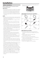
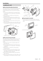
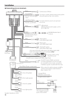
Installation Installing the unit ÑÑMounting (Using Mounting Plate) To mount the unit, you will need to find a flat surface with adequate clearance behind it that provides enough clearance for the unit and all it's necessary wiring. 1) Once you have determined a mounting location, you will need to cut a circular hole 77 mm (3inch) in diameter. 2) After the hole is cut slide the unit and wiring through the hole. 3) Slide the mounting plate (accessory 2) over the backside of the unit and secure with the supplied screws (accessory 4). 4) Press on the trim plate (accessory 1) to the front side of the unit. 5) Plug in all wiring harnesses and cables. Refer to the wiring diagram for wire harness connection types. 2 Panel (Max. 8 mm) 53 5 1 6 M4 × 37 mm Panel (Max. 15 mm) ÑÑRemoving the trim plate 1) Use the extraction key (accessory 8) to lever out the four tabs (two on the left part, two on the right part). 8 1 2) Pull the trim plate forward. 4 M3.5 × 25 mm ÑÑMounting (Using U Bracket) To mount the unit, you will need to find a flat surface with adequate clearance behind it that provides enough clearance for the unit and all it's necessary wiring. 1) Attach the screw with nut (accessory 6) to the back of the unit. 2) Once you have determined a mounting location, you will need to cut a circular hole 77 mm (3inch) in diameter. 3) After the hole is cut slide the unit and wiring through the hole. 4) Take the bracket (accessory 3) and slide over the two studs on the back of the unit. Tighten down with supplied nuts (accessory 5). 5) Press on the trim plate (accessory 1) to the front side of the unit. 6) Plug in all wiring harnesses and cables. Refer to the wiring diagram for wire harness connection types. English | 15
-
 1
1 -
2
-
3
-
4
-
5
-
6
-
7
-
8
-
9
-
 10
10 -
 11
11 -
 12
12 -
 13
13 -
 14
14 -
 15
15 -
 16
16 -
 17
17 -
 18
18 -
 19
19 -
 20
20 -
21
-
22
-
23
-
24
-
25
-
26
-
27
-
28
-
29
-
30
-
31
-
32
-
33
-
34
-
35
-
36
-
37
-
38
-
39
-
40
-
41
-
42
-
43
-
44
-
45
-
46
-
47
-
48
-
49
-
50
-
51
-
52
-
53
-
54
-
55
-
56
-
57
-
58
-
59
-
60
-
61
-
62
-
63
-
64
 |
 |
