Kenwood KRC-265L User Manual - Page 25
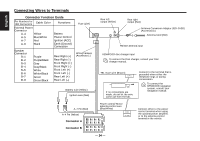
Ignition cable Red, A-4 Pin Yellow
 |
View all Kenwood KRC-265L manuals
Add to My Manuals
Save this manual to your list of manuals |
Page 25 highlights
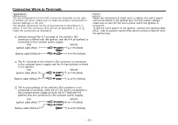
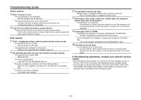
Connecting Wires to Terminals 2WARNING Connecting the ISO Connector (see p.24) The pin arrangement for the ISO connectors depends on the type of vehicle you drive. Make sure to make the proper connections to prevent damage to the unit. The default connection for the wiring harness is described in 1 below. If the ISO connector pins are set as described in 2 or 3, make the connection as illustrated. 1 (Default setting) The A-7 pin (red) of the vehicle's ISO connector is linked with the ignition, and the A-4 pin (yellow) is connected to the constant power supply. Unit Vehicle Ignition cable (Red) A-7 Pin (Red) Battery cable (Yellow) A-4 Pin (Yellow) NOTE When the connection is made as in 3 above, the unit's power will not be linked to the ignition key. For that reason, always make sure to turn off the unit's power when the ignition is turned off. To link the unit's power to the ignition, connect the ignition cable (ACC...red) to a power source that can be turned on and off with the ignition key. 2 The A-7 pin (red) of the vehicle's ISO connector is connected to the constant power supply, and the A-4 pin (yellow) is linked to the ignition. Unit Vehicle Ignition cable (Red) A-7 Pin (Red) Battery cable (Yellow) A-4 Pin (Yellow) 3 The A-4 pin (yellow) of the vehicle's ISO connector is not connected to anything, while the A-7 pin (red) is connected to the constant power supply (or both the A-7 (red) and A-4 (yellow) pins are connected to the constant power supply). Unit Ignition cable (Red) Vehicle A-7 Pin (Red) Battery cable (Yellow) A-4 Pin (Yellow) - 25 -
-
 1
1 -
2
-
3
-
4
-
5
-
6
-
7
-
8
-
9
-
10
-
11
-
12
-
13
-
14
-
15
-
16
-
17
-
18
-
19
-
 20
20 -
 21
21 -
 22
22 -
 23
23 -
 24
24 -
 25
25 -
 26
26 -
 27
27 -
 28
28 -
 29
29 -
 30
30 -
31
-
32
 |
 |
