Kenwood KRC-266S User Manual - Page 15
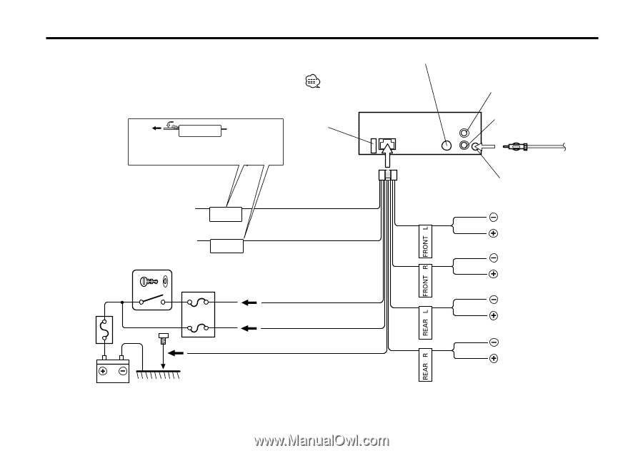
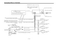
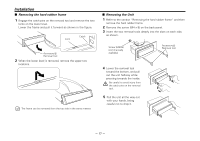
Connecting Wires to Terminals, If no connections are made, do not let, the wire come out from the tab.
 |
View all Kenwood KRC-266S manuals
Add to My Manuals
Save this manual to your list of manuals |
Page 15 highlights
Connecting Wires to Terminals KENWOOD disc changer control input2 To connect the Disc changer, consult your Disc changer manual. 3 Rear left output (White) 23 If no connections are made, do not let the wire come out from the tab.4 Fuse (10A) 24 Rear right output (Red) 28 5 When using the optional power amplifier, connect to its power control terminal. 7 Depending on what antenna you are using, connect either to the control terminal of the motor antenna, or to the power terminal for the booster amplifier of the film-type antenna. P.CONT Power control wire (Blue/White) ANT.CONT Motor antenna control wire (Blue) Ignition key switch 10 Car fuse box (Main fuse) 11 ACC 13 Car fuse box 14 Ignition wire (Red) 20 Battery wire (Yellow) 21 Ground wire (Black) · (To car chassis) 22 Battery 12 Wiring harness (Accessory1)25 FM/AM antenna input 1 29 White/Black White 32 31 Gray/Black Gray 35 34 Green/Black Green 38 37 Purple/Black Purple 40 To front left speaker 30 To front right speaker 33 To rear left speaker 36 To rear right speaker 39 - 15 -
-
 1
1 -
2
-
3
-
4
-
5
-
6
-
7
-
8
-
9
-
 10
10 -
 11
11 -
 12
12 -
 13
13 -
 14
14 -
 15
15 -
 16
16 -
 17
17 -
 18
18 -
 19
19 -
 20
20 -
21
 |
 |