Kenwood KSC-SW11 Instruction Manual - Page 6
Installation - remote
 |
View all Kenwood KSC-SW11 manuals
Add to My Manuals
Save this manual to your list of manuals |
Page 6 highlights
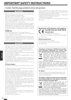
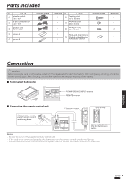
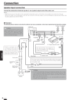
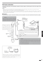
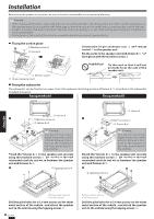
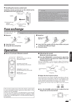
Installation Before fixing the speaker in its position, be sure to check the sound while it is connected preliminary. Caution: • When making a hole under a seat, inside the trunk, or somewhere else in the vehicle, check that there is nothing hazardous on the opposite side such as a gasoline tank, brake pipe; or wiring harness, and be careful not to cause scratches or other damage. • Install in a location that does not come in the way of driving, getting in or out of the vehicle and movement inside the ve- hicle compartment. • Fix the product firmly so that it will not be moved by vibrations or impacts during driving. ■ Fixing the cord in place 8 Machine screw x 2 5 Fixture B Connect the 10-pin connector cord 2 and remote control 1 to the speaker unit. Fix the cords to the speaker unit with fixture B 5 and fix in place with the machine screws 8. Prohibition! Fix the cord so that it will not protrude from the side of the speaker unit. 1 Remote control 2 10-pin connector cord ■ Fixing the subwoofer The subwoofer can be fixed in two ways. Select the optimum attaching position of fixture A 4 according to the subwoofer installation location. Fixing method A Fixing method B 4 Fixture A 1 7 Machine screw x 4 4 Fixture A x 2 Caution: This portion becomes slightly hotter than other portions because it functions as the radiator of the heat generated by the amplifier. Attach the fixtures A 4 to the speaker unit securely using the machine screws 7. Be careful so that the connected cords do not get in between the speaker unit and fixtures A 4. 2 6 Tapping screw x 4 4 Fixture A 1 7 Machine screw x 4 4 Fixture A x 2 Caution: This portion becomes slightly hotter than other portions because it functions as the radiator of the heat generated by the amplifier. Attach the fixtures A 4 to the speaker unit securely using the machine screws 7. Be careful so that the connected cords do not get in between the speaker unit and fixtures A 4. 2 6 Tapping screw x 4 ENGLISH Drill four pilot holes for ø 3.6 mm screws. Drill the pilot holes for ø 3.6 mm screws on the sheet metal section of the vehicle , and attach the speaker unit to the vehicle using the tapping screws 6. 6 English Drill four pilot holes for ø 3.6 mm screws. Drill the pilot holes for ø 3.6 mm screws on the sheet metal section of the vehicle , and attach the speaker unit to the vehicle using the tapping screws 6.
-
 1
1 -
 2
2 -
 3
3 -
 4
4 -
 5
5 -
 6
6 -
 7
7 -
 8
8 -
 9
9
 |
 |
