Kenwood TM-V7E User Manual - Page 94
Troubleshooting
 |
View all Kenwood TM-V7E manuals
Add to My Manuals
Save this manual to your list of manuals |
Page 94 highlights
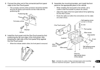
TROUBLESHOOTING 1 The problems described in this table are commonly encountered operational malfunctions. These types of difficulties are 2 usually caused by improper hook-up, accidental incorrect control settings, or operator error due to incomplete programming. These problems are usually not caused by circuit failure. Please review this table, and the appropriate section(s) of this 3 instruction manual, before assuming your transceiver is defective. 4 Note: When 2 frequencies are received in the same band and these frequencies have relationships per the equation below or other similar relationships, an internal heterodyne may be heard. This is not a defect. 5 VHF/UHF mode: (UHF receive frequency - 45.05 MHz) x 2 - (VHF receive frequency + 38.85 MHz) x 4 = 38.85 MHz or 45.05 MHz 6 (UHF receive frequency - 45.05 MHz) - (VHF receive frequency + 38.85 MHz) x 2 = 38.85 MHz VHF/VHF mode: (VHF receive frequency on the UHF band + 45.05 MHz) x 5 - (VHF receive frequency on the VHF band + 38.85 MHz) x 5 = 38.85 MHz or 45.05 MHz 7 (VHF receive frequency on the UHF band + 45.05 MHz) x 4 - (VHF receive frequency on the VHF band + 38.85 MHz) x 4 = 38.85 MHz (VHF receive frequency on the VHF band + 38.85 MHz) - (VHF receive frequency on the UHF band + 45.05 MHz) x 0.75 = 38.85 MHz 8 UHF/UHF mode: (UHF receive frequency on the VHF band - 38.85 MHz) x 3 - (UHF receive frequency on the UHF band - 45.05 MHz) x 3 = 38.85 MHz or 45.05 MHz 9 (UHF receive frequency on the VHF band - 38.85 MHz) x 4 - (UHF receive frequency on the UHF band - 45.05 MHz) x 4 = 38.85 MHz or 45.05 MHz 10 Problem Probable Cause Corrective Action Page Ref. 11 The transceiver will not 1 The power cable was connected 1 Connect the supplied DC power cable 3, 4 12 power up after connecting a 13.8 V DC power supply backwards. correctly: Red ➞ ( + ); Black ➞ ( - ). 13 14 15 and pressing the (POWER) switch. Nothing appears on the display. 2 One or more of the power cable fuses are open. 2 Look for the cause of the blown fuse(s). After inspecting and correcting any problems, install a new fuse(s) with the same ratings. 5 16 3 The front panel was not connected 3 Separate the front panel from the main 84 17 securely to the main unit of the transceiver. unit by using the release switch on the rear of the front panel, then lock the front 18 panel securely to the main unit by using 19 the same switch. 4 The connectorized cable was not 4 Connect the connectorized cable correctly. 3, 4 20 correctly connected. 21 88 Continued
-
 1
1 -
2
-
3
-
4
-
5
-
6
-
7
-
8
-
9
-
10
-
11
-
12
-
13
-
14
-
15
-
16
-
17
-
18
-
19
-
20
-
21
-
22
-
23
-
24
-
25
-
26
-
27
-
28
-
29
-
30
-
31
-
32
-
33
-
34
-
35
-
36
-
37
-
38
-
39
-
40
-
41
-
42
-
43
-
44
-
45
-
46
-
47
-
48
-
49
-
50
-
51
-
52
-
53
-
54
-
55
-
56
-
57
-
58
-
59
-
60
-
61
-
62
-
63
-
64
-
65
-
66
-
67
-
68
-
69
-
70
-
71
-
72
-
73
-
74
-
75
-
76
-
77
-
78
-
79
-
80
-
81
-
82
-
83
-
84
-
85
-
86
-
87
-
88
-
 89
89 -
 90
90 -
 91
91 -
 92
92 -
 93
93 -
 94
94 -
 95
95 -
 96
96 -
 97
97 -
 98
98 -
 99
99 -
100
 |
 |
