Kenwood TS-570D User Manual - Page 63
Installing Options
 |
View all Kenwood TS-570D manuals
Add to My Manuals
Save this manual to your list of manuals |
Page 63 highlights
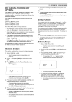
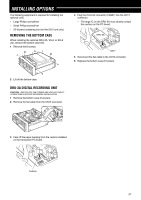
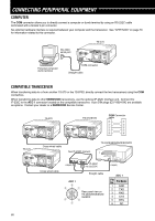
INSTALLING OPTIONS The following equipment is required for installing the optional units. • Large Philips screwdriver • Small Philips screwdriver • 25 W pencil soldering iron (for the SO-2 unit only) REMOVING THE BOTTOM CASE When installing the optional DRU-3A, VS-3, or SO-2 unit, remove the bottom case first. 1 Remove the 8 screws. 4 Plug the DRU-3A connector (CN901) into the CN17 connector. • The large IC on the DRU-3A must closely contact the cushion on the PC board. DRU-3A CN17 5 Reconnect the flat cable to the CN15 connector. 6 Replace the bottom case (8 screws). 2 Lift off the bottom case. DRU-3A DIGITAL RECORDING UNIT CAUTION: SWITCH OFF THE POWER AND UNPLUG THE DC POWER CABLE BEFORE BEGINNING INSTALLATION. 1 Remove the bottom case (8 screws). 2 Remove the flat cable from the CN15 connector. CN15 3 Peel off the paper backing from the cushion installed on the transceiver PC board. Cushion 57
-
 1
1 -
2
-
3
-
4
-
5
-
6
-
7
-
8
-
9
-
10
-
11
-
12
-
13
-
14
-
15
-
16
-
17
-
18
-
19
-
20
-
21
-
22
-
23
-
24
-
25
-
26
-
27
-
28
-
29
-
30
-
31
-
32
-
33
-
34
-
35
-
36
-
37
-
38
-
39
-
40
-
41
-
42
-
43
-
44
-
45
-
46
-
47
-
48
-
49
-
50
-
51
-
52
-
53
-
54
-
55
-
56
-
57
-
 58
58 -
 59
59 -
 60
60 -
 61
61 -
 62
62 -
 63
63 -
 64
64 -
 65
65 -
 66
66 -
 67
67 -
 68
68 -
69
-
70
-
71
-
72
-
73
-
74
-
75
-
76
-
77
-
78
-
79
-
80
-
81
-
82
-
83
-
84
-
85
-
86
-
87
-
88
-
89
 |
 |
