Kenwood VR 3080 Service Manual - Page 4
Disassembly For Repair - krf v7772d
 |
UPC - 019048106308
View all Kenwood VR 3080 manuals
Add to My Manuals
Save this manual to your list of manuals |
Page 4 highlights
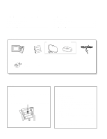
KRF-V7772D/VR-3080 DISASSEMBLY FOR REPAIR [Check the audio PCB(X09)] 1. Remove the 9 screws (1,2,3). 2. Remove the 4 hooks(4,5) and remove the audio PCB(X09),then stand the set with left side downward. 3. Connect between the chassis of the set and the rear panel with an alligator clip lead wire (6). HOOK 4 1 x2 X09- 3 x4 6 5 HOOK 2 x3 [Check the B side of the DSP PCB (X08)] 3 X08- 1. Remove the 11 screws(1,2). 2. Remove the X08(C/10)(J/10) (3 ), then remove the X08(A/10) (4). 3. Solder the pin 1(-17V), the pin 4 (+17V) and the pin 6(GND) between CN1 on the X08(A/10) and CN2 on the X08(I/10) with 3 1 x2 6 lead wires (5). 4 6 6 4. Connect between the each GND of J1, J62, J61, J2 on the X08(A/10)and the rear panel X08B side with 4 alligator clip lead wires (6). 5 6 4 1 Fig. 1 6 14 6 4 [Remove the escutcheon (operation panel)] 2 x7 2 x2 Fig. 2 1. Remove the knob(1), the nut (2), the 11 screws(3, 4, 5) and 2 hooks (6), then 6 remove the front panel ass'y. 7 2. Remove the lead wire(7), the 2 screws(8 : except K,P type) and 7 screws(9) then remove the PCB. 6 8 x2 3. Remove the under front glass(0, -), then 1 remove the front panel(=) from the sub 3 panel. 4. Remove the 2 under escutcheon sides(~) by 3 x2 34 3 9 x5 9 · screw driver and the 2 hooks(!) then 12 remove the escutcheon(@). 9 5 x2 4 2 43 10 13 14 11 14 13 13 15 4 Fig. 3
-
 1
1 -
 2
2 -
 3
3 -
 4
4 -
 5
5 -
 6
6 -
 7
7 -
 8
8 -
 9
9 -
 10
10 -
11
-
12
-
13
-
14
-
15
-
16
-
17
-
18
-
19
-
20
-
21
-
22
-
23
-
24
-
25
-
26
-
27
-
28
-
29
-
30
-
31
-
32
-
33
-
34
-
35
-
36
-
37
-
38
-
39
-
40
 |
 |
