KitchenAid KCMS1655BSS Installation Guide - Page 5
Install Trim Kit Frame - with trim kit
 |
View all KitchenAid KCMS1655BSS manuals
Add to My Manuals
Save this manual to your list of manuals |
Page 5 highlights
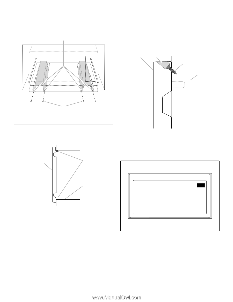
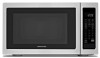
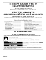
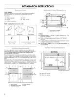
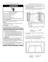
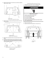
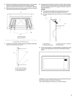
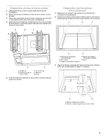
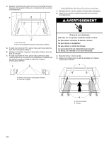
5. Slide the microwave oven back and into place. The mounting holes of the rail flanges and bottom duct flange will align against the bottom front facing of the cutout/cabinet opening. 6. Secure the microwave oven to the cutout/cabinet by installing four short screws into the mounting holes. A 2. Holding the trim kit frame in place, use 7/64" drill to drill four pilot holes into the front facing of the cutout/cabinet through the mounting hole guides in the upper and lower corners of the trim kit frame. NOTES: ■ The holes will be drilled downward from the top, and upward from the bottom at an angle of about 45°. ■ To avoid damage to the trim kit frame, do not overtighten screws. A B C D B A. Mounting holes B. Short screws (4) Install Trim Kit Frame 1. Position trim kit frame over the opening so that the lower tabs rest on the cutout floor, as shown. A B A. Trim kit frame B. Mounting hole guide C. Long wood screw (4 - painted) D. Cutout ceiling 3. Secure trim kit frame to cutout/cabinet by installing four long wood screws (painted) into the pilot holes drilled in Step 2 above. C A. Front of trim kit frame B. Tabs (upper and lower) C. Cutout/cabinet floor Installation is now complete. Replace any loose items that have been removed from microwave oven cavity. Save these Installation Instructions for future reference. 5
-
 1
1 -
 2
2 -
 3
3 -
 4
4 -
 5
5 -
 6
6 -
 7
7 -
 8
8 -
 9
9 -
 10
10 -
 11
11 -
12
 |
 |