KitchenAid KUIC18PNTS Use and Care Guide - Page 5
Drain Connection - parts
 |
UPC - 883049049885
View all KitchenAid KUIC18PNTS manuals
Add to My Manuals
Save this manual to your list of manuals |
Page 5 highlights
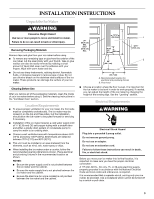
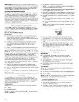
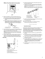
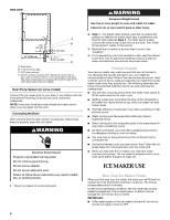
NOTE: To allow sufficient water flow to the ice maker a minimum ¹⁄₂" size copper supply line is recommended. A B 6. Remove and discard the short, black plastic tube from the end of the water line inlet. 7. Thread the nut onto the coupling on the end of the tubing. Tighten the nut by hand. Then tighten it with a wrench two more turns. Do not overtighten. NOTE: To avoid rattling, be sure the copper tubing does not touch the cabinet's side wall or other parts inside the cabinet. A. Bulb B. Nut 3. Now you are ready to connect the copper tubing. Use ¹⁄₄" (6.35 mm) OD soft copper tubing for the cold water supply. ■ Ensure that you have the proper length needed for the job. Be sure both ends of the copper tubing are cut square. ■ Slip compression sleeve and compression nut on copper tubing as shown. Insert end of tubing into outlet end squarely as far as it will go. Screw compression nut onto outlet end with adjustable wrench. Do not overtighten. AB A. Compression sleeve B. Compression nut D C C. Copper tubing D. Coupling (purchased) 4. Place the free end of the tubing into a container or sink, and turn on main water supply and flush out tubing until water is clear. Turn off shutoff valve on the water pipe. NOTE: Always drain the water line before making the final connection to the inlet of the water valve to avoid possible water valve malfunction. 5. Bend the copper tubing to meet the water line inlet which is located on the back of the ice maker cabinet as shown. Leave a coil of copper tubing to allow the ice maker to be pulled out of the cabinet or away from the wall for service. REAR VIEW A B C D AB C D EF G A. Line to ice maker B. Nut (purchased) C. Ferrule (purchased) D. Coupling (purchased) E. Ferrule F. Nut G. Supplied line from ice maker 8. Install the water supply tube clamp around the water supply line to reduce strain on the coupling. 9. Turn shutoff valve ON. 10. Check for leaks. Tighten any connections (including connections at the valve) or nuts that leak. Drain Connection Gravity Drain System Connect the ice maker drain to your drain in accordance with all state and local codes and ordinances. If the ice maker is provided with a gravity drain system, follow these guidelines when installing drain lines. This will help keep water from flowing back into the ice maker storage bin and potentially flowing onto the floor causing water damage. ■ Drain lines must have a minimum of 15.88 mm) inside diameter. ■ Drain lines must have a 1" drop per 48" (2.54 cm drop per 122 cm) of run or ¹⁄₄" drop per 12" (6.35 mm per 30.48 cm) of run and must not have low points where water can settle. ■ The floor drains must be large enough to accommodate drainage from all drains. ■ The ideal installation has a standpipe with a 1¹⁄₂" (3.81 cm) to 2" (5.08 cm) PVC drain reducer installed directly below the outlet of the drain tube as shown. You must maintain a 1" (2.54 cm) air gap between the drain hose and the standpipe. ■ It may be desirable to insulate the drain line thoroughly up to the drain inlet. E A. Water supply tube clamp B. Vent hose (drain pump models only) C. Water supply line D. Inlet water tube clamp E. Drain hose (drain pump models only) 5
-
 1
1 -
 2
2 -
 3
3 -
 4
4 -
 5
5 -
 6
6 -
 7
7 -
 8
8 -
 9
9 -
 10
10 -
 11
11 -
12
-
13
-
14
-
15
-
16
-
17
-
18
-
19
-
20
-
21
-
22
-
23
-
24
 |
 |
