KitchenAid KVWB606DSS Installation Guide - Page 13
Make Electrical Power Supply Connection to, Range Hood
 |
View all KitchenAid KVWB606DSS manuals
Add to My Manuals
Save this manual to your list of manuals |
Page 13 highlights
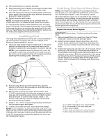
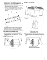
6. Connect the same color wires to each other (black to black, white to white, etc.) using UL listed wire connectors. NOTE: Connect the green (or green/yellow) ground wire from the wiring conduit to the green (or bare) ground wire from the home power supply using UL listed wire connectors (see the "Make Electrical Power Supply Connections to Range Hood" section). B C D E F A G H A. UL listed or CSA approved ¹⁄₂" (1.3 cm) wiring conduit B. UL listed wire connectors C. Black wires D. White wires I E. Red wires F. Blue wires G. Gray wires H. Green (or green/yellow) wire I. 6-wire connector assembly 7. Go to "Make Electrical Power Supply Connection to Range Hood" section. E A B C D F A. White wires B. Black wires C. UL listed wire connectors D. Green, bare or yellow/green wires E. Home power supply F. UL listed or CSA approved ¹⁄₂" (1.3 cm) strain relief 3. Use UL listed wire connectors and connect black wires (B) together. 4. Use UL listed wire connectors and connect white wires (A) together. WARNING Make Electrical Power Supply Connection to Range Hood WARNING Electrical Shock Hazard Electrically ground blower. Connect ground wire to green and yellow ground wire in terminal box. Failure to do so can result in death or electrical shock. Electrical Shock Hazard Disconnect power before servicing. Replace all parts and panels before operating. Failure to do so can result in death or electrical shock. 1. Disconnect power. 2. Locate terminal box inside of the range hood. NOTE: When using an in-line blower motor system, the green (or green/yellow) ground wire in the conduit from the In-line blower motor system is to be connected with the green (or bare) wire of the home power supply cable and with the green/yellow wire (D) in the terminal box. 5. Connect green (or bare) ground wire from home power supply to the green/yellow ground wire (D) in terminal box using UL listed wire connectors. 6. Install terminal box cover. 7. Check that all light bulbs are secure in their sockets. 8. Reconnect power. A B A. Terminal box cover B. Knockout in canopy back into terminal box 13
-
 1
1 -
2
-
3
-
4
-
5
-
6
-
7
-
 8
8 -
 9
9 -
 10
10 -
 11
11 -
 12
12 -
 13
13 -
 14
14 -
 15
15 -
 16
16 -
 17
17 -
 18
18 -
19
-
20
-
21
-
22
-
23
-
24
-
25
-
26
-
27
-
28
-
29
-
30
-
31
-
32
-
33
-
34
-
35
-
36
 |
 |
