KitchenAid KVWB606DSS Installation Guide - Page 4
Location Requirements - parts
 |
View all KitchenAid KVWB606DSS manuals
Add to My Manuals
Save this manual to your list of manuals |
Page 4 highlights
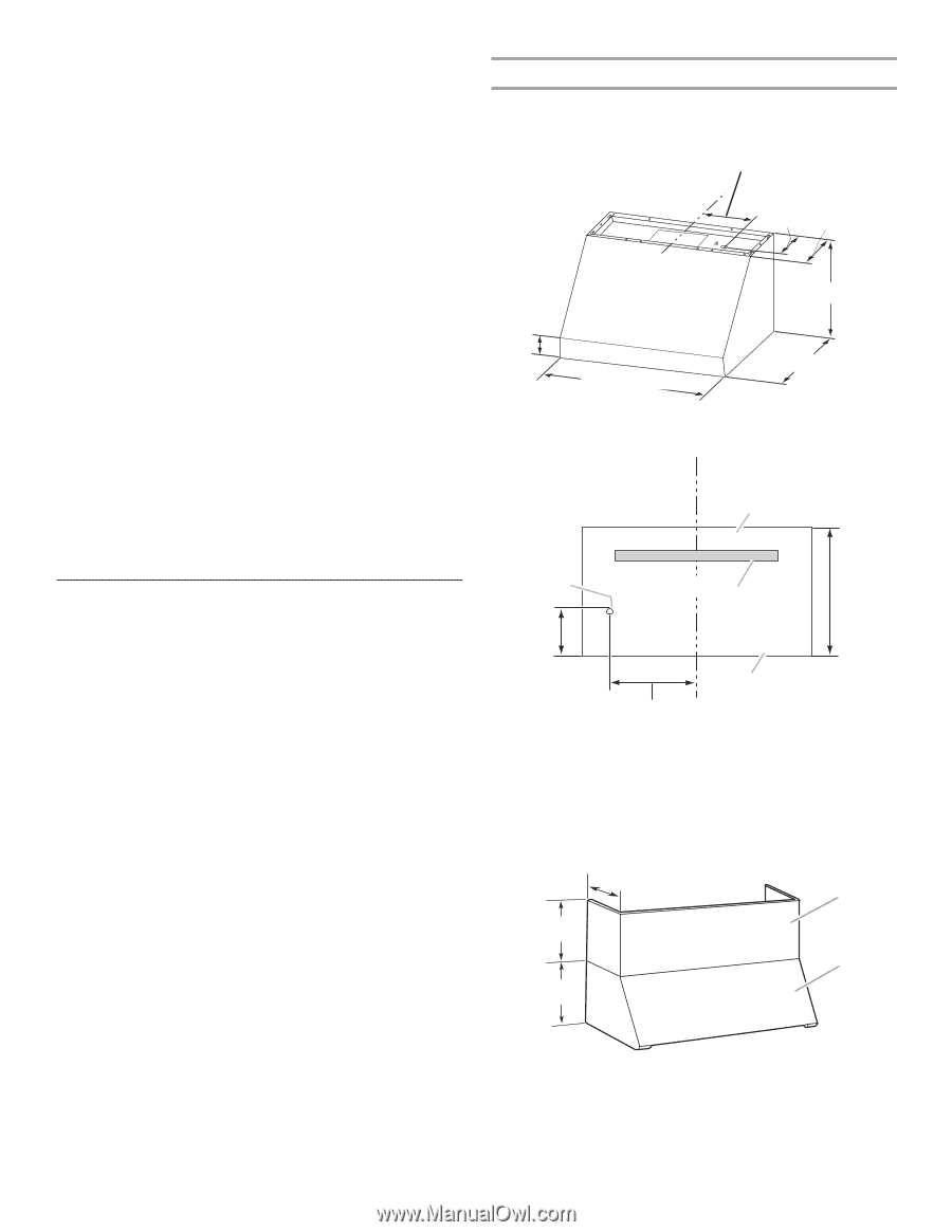
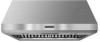
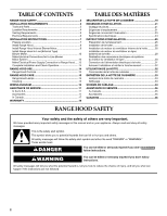
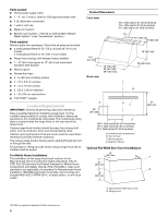
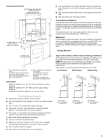
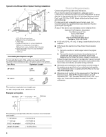
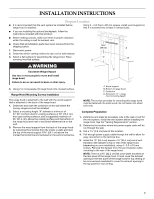
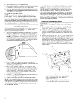
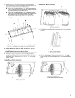
Parts needed ■ Home power supply cable ■ 1 - ½" (12.7 mm) UL listed or CSA approved strain relief ■ 3 UL listed wire connectors ■ 1 wall or roof cap ■ Metal vent system ■ Blower motor system - internal or external (See "Blower Motor System" in the "Accessories" section.) Parts supplied Remove parts from packages. Check that all parts are included. ■ 2 metal grease filters for 30" (76.2 cm) and 36" (91.4 cm) models 3 metal grease filters for 48" (121.9 cm) models ■ Range hood canopy with halogen lamps installed. ■ 1 - 10" (25.4 cm) square to 10" (25.4 cm) round duct transition with damper ■ Wood support ■ Grease drip trays ■ 4 - 6 x 80 mm mounting screws ■ 4 - 3.5 x 9.5 mm screws ■ 6 - 4.2 x 19 mm screws ■ 2 - D5.3 x 20 mm washers ■ 2 - 10 x 50 mm wall anchors ■ T-20 TORX®† adapter Location Requirements IMPORTANT: Observe all governing codes and ordinances. Have a qualified technician install the range hood. It is the installer's responsibility to comply with installation clearances specified on the model/serial rating plate. The model/serial rating plate is located inside the range hood on the rear wall of the range hood. Canopy range hood location should be away from strong draft areas, such as windows, doors and strong heating vents. Cabinet opening dimensions that are shown must be used. Given dimensions provide minimum clearance. The canopy range hood is factory set for venting through the roof or through the wall. All openings in ceiling and wall where canopy range hood will be installed must be sealed. For Mobile Home Installations The installation of this range hood must conform to the Manufactured Home Construction Safety Standards, Title 24 CFR, Part 328 (formerly the Federal Standard for Mobile Home Construction and Safety, Title 24, HUD, Part 280) or when such standard is not applicable, the standard for Manufactured Home Installation 1982 (Manufactured Home Sites, Communities and Setups) ANSI A225.1/NFPA 501A*, or latest edition, or with local codes. Product Dimensions Front view 18 45.9 cm) for 48" (121.9 cm) Hood 12 30.6 cm) for 36" (91.4 cm) Hood 9 23.0 cm) for 30" (76.2 cm) Hood CL 6¹⁄₂" (16.5 cm) 12" (30.5 cm) 3 8.1 cm) Back view 30" (76.2 cm) 36" (91.4 cm) 48" (121.9 cm) 18" (45.7 cm) 25" (63.5 cm) B A 9⁵⁄₈" (24.4 cm) CL C D 18 47.8 cm) for 48" (121.9 cm) Hood 12 32.5 cm) for 36" (91.4 cm) Hood 9 24.9 cm) for 30" (76.2 cm) Hood A. Knockout into terminal box B. Top of hood C. Wood support D. Bottom of hood Optional Full-Width Duct Cover Installations 12" (30.5 cm) 12" (30.5 cm) 18" (45.7 cm) 18" (45.7 cm) A B A. Optional full-width duct cover B. Range hood †®TORX is a registered trademark of Saturn Fasteners, Inc. 4
-
 1
1 -
 2
2 -
 3
3 -
 4
4 -
 5
5 -
 6
6 -
 7
7 -
 8
8 -
 9
9 -
 10
10 -
11
-
12
-
13
-
14
-
15
-
16
-
17
-
18
-
19
-
20
-
21
-
22
-
23
-
24
-
25
-
26
-
27
-
28
-
29
-
30
-
31
-
32
-
33
-
34
-
35
-
36
 |
 |