Kodak 120-3090 User Guide - Page 2
Patch Code Information for, Scanners - specs
 |
UPC - 041771203092
View all Kodak 120-3090 manuals
Add to My Manuals
Save this manual to your list of manuals |
Page 2 highlights
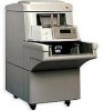
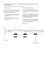
Patch Code Information for Kodak Scanners Patch description This document provides information that supports the following scanners. • Kodak Scanners 9XYZ, 5XYZ, 7XYZ, i800/i1800 (with image addressing) Series Scanners and the Kodak Microimager 70-these scanners are equipped with the Patch Reader. The Patch Reader recognizes patches with bars that are parallel to the lead edge of the document. All of these scanners may use patches for image addressing. In addition, the i800/i1800 (with image addressing) Series Scanners may use toggle patches for Color on the Fly functionality. • Kodak Scanners i280, 3590C and i600/i1800 (without image addressing) Series Scanners-these scanners are not equipped with a Patch Reader. These scanners recognize patches with bars that are perpendicular to the lead edge of the document. These scanners will only recognize the toggle patch for Color on the Fly functionality and do not have image addressing. A patch is a pattern of parallel, alternating black bars and spaces that is printed on a document. Kodak Scanners which have patch reading capability can recognize patch documents and automatically assign a document image level, increment the document image address, or perform Color on the Fly functionality. The wide bars should be 0.20 inches (5 mm) wide + 0.01 inches (0.25 mm). The narrow bars and spaces should be 0.08 inches (2.03 mm) wide + 0.01 inches (0.25 mm). The maximum width of the patch code is 0.80 inches (20 mm) +0.01 inches (0.25 mm). The minimum overall length of the patch bars is 2 inches (50 mm). NOTE: The patch codes illustrated below are not to spec. Use the patch sheets included in this packet for specifications. Patch Codes Patch code specifications Zone Inches Millimetres Patch 2 Patch 2 Low High Low High Range Range Range Range A B C D E F A 0.19 0.21 4.83 5.33 B 0.27 0.29 6.86 7.37 C 0.35 0.37 8.89 9.40 D 0.43 0.45 10.92 11.43 G E 0.51 0.53 12.95 13.46 Assigns image level 2 to the current document. F 0.59 0.61 14.99 15.49 G 0.79 0.81 20.07 20.57 Patch 3 Assigns image level 3 to the current document. Patch 3 AB CD EF G Patch T / Transfer Patch Assigns a predefined image level to the next document. The predefined image level is based upon the transfer patch definition which is defined for each applica- Patch T / Transfer Patch A B C DEF G tion. For example, if the transfer patch definition is image level 2, then use of a transfer patch assigns image level 2 to the next document. Zone A B C D E F G Inches Millimetres Low High Low High Range Range Range Range 0.19 0.21 4.83 5.33 0.27 0.29 6.86 7.37 0.35 0.37 8.89 9.40 0.43 0.45 10.92 11.43 0.63 0.65 16.00 16.51 0.71 0.73 18.03 18.54 0.79 0.81 20.07 20.57 Zone A B C D E F G Inches Millimetres Low High Low High Range Range Range Range 0.07 0.09 1.78 2.29 0.15 0.17 3.81 4.32 0.35 0.37 8.89 9.40 0.43 0.45 10.92 11.43 0.51 0.53 12.95 13.46 0.59 0.61 14.99 15.49 0.79 0.81 20.07 20.57
-
 1
1 -
 2
2 -
 3
3 -
 4
4 -
 5
5 -
 6
6 -
 7
7 -
 8
8
 |
 |
