Kodak 120-3090 User Guide - Page 4
Scanners 9XYZ, 5XYZ, 7XYZ, i800/i1800 with image addressing Series Scanners, and 70 Microimager
 |
UPC - 041771203092
View all Kodak 120-3090 manuals
Add to My Manuals
Save this manual to your list of manuals |
Page 4 highlights
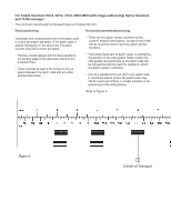
For Kodak Scanners 9XYZ, 5XYZ, 7XYZ, i800/i1800 (with image addressing) Series Scanners and 70 Microimager: The minimum overall length of the patch bars is 2 inches (50 mm). Patch positioning Horizontal placement/positioning Horizontal and vertical placement of the patch code is critical for proper operation. If the patch code is placed improperly on the document, the patch sensors may fail to sense the patch. • Patches should appear with the bars parallel to the leading edge of the document (fed into the transport first). • There must be at least 0.25 inches (6 mm) of space between the patch code and any other printed information. • There are five patch sensor locations for the scanner models listed above, except for the i1800 Series Scanners which have four patch sensor locations. • Horizontal placement of patch codes is affected by the position of the side guides. Make certain the side guides are positioned so the patch code will be transported directly past the window in which the patch reader is installed. • Use of a standard 2.5-inch (62.5 mm) patch code is recommended to ensure the patch code may still be read even if there is a slight variation in the positioning of the side guide(s). Refer to Figure A. Figure A Center of Transport
-
 1
1 -
 2
2 -
 3
3 -
 4
4 -
 5
5 -
 6
6 -
 7
7 -
 8
8
 |
 |
