Konica Minolta magicolor 1600W Service Manual - Page 43
Image creation process - negative
 |
View all Konica Minolta magicolor 1600W manuals
Add to My Manuals
Save this manual to your list of manuals |
Page 43 highlights
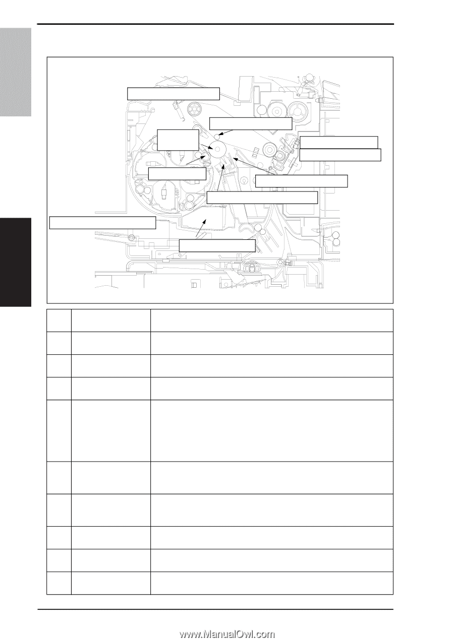
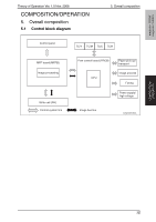
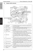
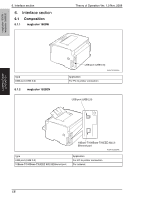
5. Overall composition 5.2 Image creation process Theory of Operation Ver. 1.0 Nov. 2008 magicolor 1600W magicolor 1650EN COMPOSITION/ OPERATION [9] Transfer belt cleaning [2] Photo conductor [6] 1st image transfer [8] Media separation [7] 2nd image transfer [5] Developing [10] PC drum cleaning [3] Photo conductor charging [1] Printer image processing [4] Laser exposure A00VT1C005AA [1] Printer image processing • The intensity of the laser light is controlled by the image signal sent from the host computer. [2] Photo conductor • The image projected onto the surface of the photo conductor is converted to a corresponding electrostatic latent image. [3] Photo conductor charging • A negative DC charge layer is formed on the surface of the photo conductor. [4] Laser exposure • The surface of the photo conductor is irradiated with the laser light and an electrostatic latent image is thereby formed. [5] Developing • The toner, negatively charged in the Hopper, is attracted onto the electrostatic latent image formed on the surface of the photo conductor. It is thereby changed to a visible, developed image. • A DC negative bias voltage is applied to the Developing roller, thereby preventing toner from sticking to the background image portion. [6] 1st image transfer • A DC positive voltage is applied to the backside of the transfer belt, thereby allowing the visible, developed image on the surface of the photo conductor to be transferred onto the transfer belt. [7] 2nd image transfer • A DC positive voltage is applied to the backside of the media, thereby allowing the visible, developed image on the surface of the transfer belt to be transferred onto the media. [8] Media separation • The media, which has undergone the 2nd image transfer process, is neutralized. [9] Transfer belt cleaning • A charge is applied to the transfer belt. By potential difference, residual toner on the surface of the transfer belt is collected for cleaning. [10] Photo conductor cleaning • The residual toner left on the surface of the photo conductor is scraped off. 16
-
 1
1 -
2
-
3
-
4
-
5
-
6
-
7
-
8
-
9
-
10
-
11
-
12
-
13
-
14
-
15
-
16
-
17
-
18
-
19
-
20
-
21
-
22
-
23
-
24
-
25
-
26
-
27
-
28
-
29
-
30
-
31
-
32
-
33
-
34
-
35
-
36
-
37
-
 38
38 -
 39
39 -
 40
40 -
 41
41 -
 42
42 -
 43
43 -
 44
44 -
 45
45 -
 46
46 -
 47
47 -
 48
48 -
49
-
50
-
51
-
52
-
53
-
54
-
55
-
56
-
57
-
58
-
59
-
60
-
61
-
62
-
63
-
64
-
65
-
66
-
67
-
68
-
69
-
70
-
71
-
72
-
73
-
74
-
75
-
76
-
77
-
78
-
79
-
80
-
81
-
82
-
83
-
84
-
85
-
86
-
87
-
88
-
89
-
90
-
91
-
92
-
93
-
94
-
95
-
96
-
97
-
98
-
99
-
100
-
101
-
102
-
103
-
104
-
105
-
106
-
107
-
108
-
109
-
110
-
111
-
112
-
113
-
114
-
115
-
116
-
117
-
118
-
119
-
120
-
121
-
122
-
123
-
124
-
125
-
126
-
127
-
128
 |
 |