Konica Minolta magicolor plus magicolor plus Copyboard M-12S/M-12W/M-125 User - Page 10
Rear
 |
View all Konica Minolta magicolor plus manuals
Add to My Manuals
Save this manual to your list of manuals |
Page 10 highlights
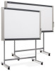
Names of the Parts Rear DC input connector Connect this with the DC plug end of the AC power adapter. (See Page E-37.) (Only connect the supplied AC power adapter; nothing else.) Personal computer (PC) dedicated USB port (Type B) Connect this with the USB port (type A) of the PC. (See Page E-37.) Special software can be used to transfer image data directly to the computer and set the copyboard's operating environment. To use these functions, first install the drivers and software on the included CD-ROM onto the computer. (See the separate software operation manual.) Printer connector (USB port Type A) Connect this with the USB connector of the printer (See Page E-37). (The printer connector is dedicated for use with a printer; use it only with a printer.) The connector is located on the bottom surface of the main unit. The diagram view is seen from the bottom. * This illustration does not show the printer or connection cords. Locking and unlocking the casters of the stand* Lock the casters with the stopper after setup. To move the unit, remove the stabilizers and release the caster stopper. Press the bottom of the stopper to lock it. Press the top to release it. Unlock Lock Stabilizer E-10 Caster
-
 1
1 -
2
-
3
-
4
-
 5
5 -
 6
6 -
 7
7 -
 8
8 -
 9
9 -
 10
10 -
 11
11 -
 12
12 -
 13
13 -
 14
14 -
 15
15 -
16
-
17
-
18
-
19
-
20
-
21
-
22
-
23
-
24
-
25
-
26
-
27
-
28
-
29
-
30
-
31
-
32
-
33
-
34
-
35
-
36
-
37
 |
 |
