LG 22LG3DCH Owners Manual - Page 26
Pillowspeakersetup - lcd
 |
UPC - 719192174368
View all LG 22LG3DCH manuals
Add to My Manuals
Save this manual to your list of manuals |
Page 26 highlights
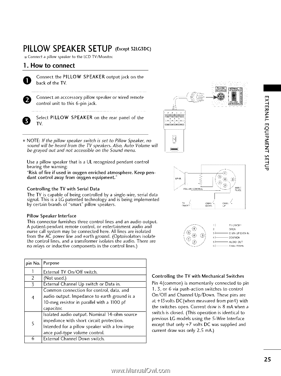
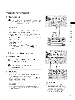
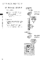
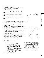
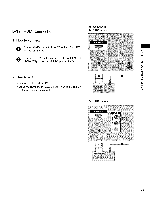
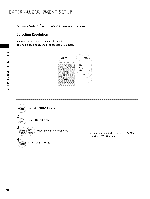
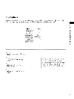
PILLOW SPEAKERSETUP (Except 32LG3DC) Connect a pillow speaker to the LCD TV/Monitor. I. How to connect O Cbaocnkneocft thtehe TVP.ILLOW SPEAKER output jack on the O onnect an acccessory pillow speaker or wired remote control unit to this 6-pin jack. O STVel.ect PILLOW SPEAKER on the rear panel of the I_--_ :r_ > _ NOTE: If the pillow speaker switch is set to Pillow Speaker, no sound will be heard from the TV speakers. Also, Auto Volume will be grayed out and not accessible on the Sound menu. Use a pillow speaker that is a UL recognized pendant bearing the warning: "Risk of fire if used in oxygen enriched atmosphere. dant control away from oxygen equipment." control Keep pen- Controlling the TV with Serial Data The TV is capable of being controlled by a single-wire, serial data signal. This is a LG patented technology and is being implemented by certain brands of "smart" pillow speakers. Pillow Speaker Interface This connector furnishes three control lines and an audio output. A patient-pendant remote control, or entertainment audio and nurse call system may be connected here. All lines are isolated from the AC power line and earth ground. (Optoisolators isolate the control lines, and a transformer isolates the audio. There are no relays or inductive components in the control lines.) r'rl x .-I I-I1 z > I'rl ,O c I-I1 z .-I !,/'1 I-I1 -t c 1_ TV ON/OFF 2 OPEN 3_ CHAN UP/DATA UN 4_ COMMON 5_ AUDUO OUT 6_ CHAU DOWN pin No. Purpose 1 External TV On/Off switch. 2 (Not used.) 3 External Channel Up switch or Data in. Common connection for control, data, and 4 audio output. Impedance to earth ground is a 10-meg resistor in parallel with a 1100 pf capacitor. Isolated audio output. Nominal 14-ohm source 5 impedance with short circuit protection. Intended for a pillow speaker with a Iow-impe ance pad-type volume control. 6 External Channel Down switch. Controlling the TV with Mechanical Switches Pin 4(common) is momentarily connected to pin 1,3, or 6 via push-action switches to control On/Off and Channel Up/Down. These pins are at +13volts DC(when measured from pin4) with the switches open. Current draw is 8 mA when a switch is closed. (This operation is identical to previous LG models using the 5-Wire Interface except that only +7 volts DC was supplied and current draw was only 2.5 mA.) 2S
-
 1
1 -
2
-
3
-
4
-
5
-
6
-
7
-
8
-
9
-
10
-
11
-
12
-
13
-
14
-
15
-
16
-
17
-
18
-
19
-
20
-
 21
21 -
 22
22 -
 23
23 -
 24
24 -
 25
25 -
 26
26 -
 27
27 -
 28
28 -
 29
29 -
 30
30 -
 31
31 -
32
-
33
-
34
-
35
-
36
-
37
-
38
-
39
-
40
-
41
-
42
-
43
-
44
-
45
-
46
-
47
-
48
-
49
-
50
-
51
-
52
-
53
-
54
-
55
-
56
-
57
-
58
-
59
-
60
-
61
-
62
-
63
-
64
-
65
-
66
-
67
-
68
-
69
-
70
-
71
-
72
-
73
-
74
-
75
-
76
-
77
-
78
-
79
-
80
-
81
-
82
-
83
-
84
-
85
-
86
-
87
 |
 |