LG 37LC51 Owner's Manual - Page 8
BACK PANEL INFORMATION, Plasma TV Models
 |
View all LG 37LC51 manuals
Add to My Manuals
Save this manual to your list of manuals |
Page 8 highlights
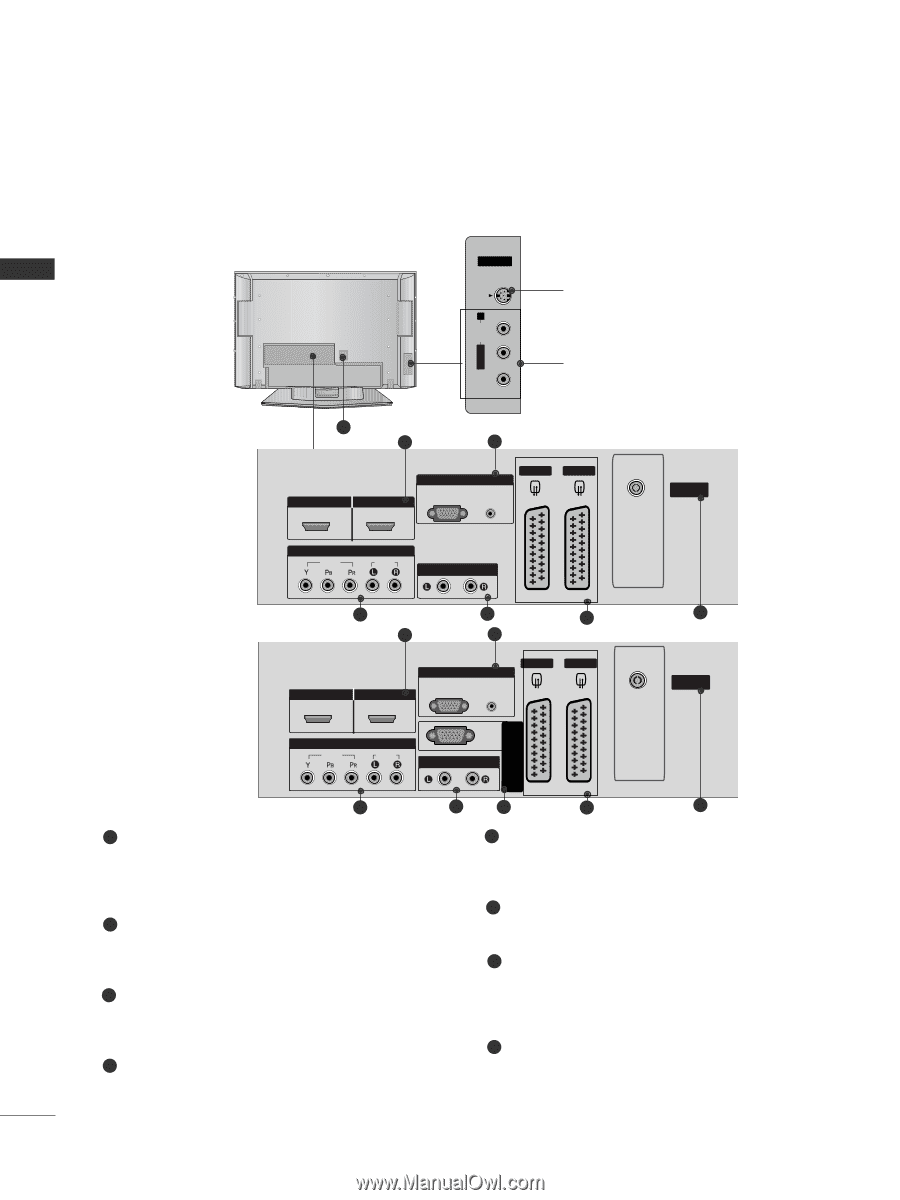
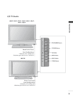
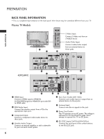
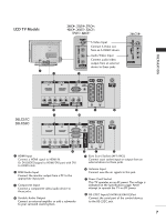
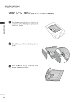
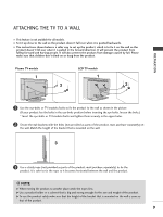
PREPARATION PREPARATION BACK PANEL INFORMATION I This is a simplified representation of the back panel. Here shown may be somewhat different from your TV. Plasma TV Models AV IN 3 VIDEO L/MONO AUDIO R S-VIDEO VIDEO L/MONO AUDIO R S-VIDEO VIDEO L/MONO AUDIO R S-VIDEO AV IN 3 AV IN 3 7 1 2 HDMI/DVI IN 1 HDMI IN 2 COMPONENT IN VIDEO AUDIO RGB IN HDMI/DVI IN 1 HDMI IN 2 COMPONREGNTBIN IN VIDEO AUDIO HDMI/DVI INAV 1 1 VARIABLE AUDIO OUT AV 1 AV 2 HDMAI VIN2 2 ANTENNA IN RGB IN RGB AUDIO (PC) (RGB/DVI) AV 1 ANTENNA IN COMPONENT IN VIDEO AUDIO VARIABLE AUDIO OUT VARIABLE AUDIO OUT 3 4 42PC5RVC 1 HDMI/DVI IN 1 HDMI IN 2 2 AV 1 RGB IN RGB AUDIO (PC) (RGB/DVI) S-Video Input Connect S-Video out from an S-VIDEO device. Audio/Video Input Connect audio/video output from an external device to these jacks. AV IN 3 AV 2 ANTENNA IN VIDEO L/MONO AUDIO R S-VIDEO 5 AV 2 6 ANTENNA IN COMPONENT IN VIDEO AUDIO VARIABLE AUDIO OUT RS-232C IN (CONTROL & SERVICE) 3 4 1 HDMI Input Connect a HDMI signal to HDMI IN. Or DVI(VIDEO)signal to HDMI/DVI port with DVI to HDMI cable. 2 RGB/Audio Input Connect the monitor output from a PCto the appropriate input port. 3 Component Input Connect a component video/audio device to these jacks. 4 Variable Audio Output Connect an external amplifier or add a subwoofer to your surround sound system. 8 5 6 5 Euro Scart Socket (AV1/AV2) Connect scart socket input or output from an external device to these jacks. 6 Antenna Input Connect over-the-air signals to this jack. 7 Power Cord Socket This TV operates on an AC power. The voltage is indicated on the Specifications page. Never attempt to operate the TV on DC power. 8 RS-232C Input(CONTROL&SERVICE)Port Connect the serial port of the control devices to the RS-232C jack. 6
-
 1
1 -
2
-
 3
3 -
 4
4 -
 5
5 -
 6
6 -
 7
7 -
 8
8 -
 9
9 -
 10
10 -
 11
11 -
 12
12 -
 13
13 -
14
-
15
-
16
-
17
-
18
-
19
-
20
-
21
-
22
-
23
-
24
-
25
-
26
-
27
-
28
-
29
-
30
-
31
-
32
-
33
-
34
-
35
-
36
-
37
-
38
-
39
-
40
-
41
-
42
-
43
-
44
-
45
-
46
-
47
-
48
-
49
-
50
-
51
-
52
-
53
-
54
-
55
-
56
-
57
-
58
-
59
-
60
-
61
-
62
-
63
-
64
-
65
-
66
-
67
-
68
-
69
-
70
-
71
-
72
-
73
-
74
-
75
-
76
-
77
-
78
-
79
-
80
-
81
-
82
-
83
-
84
 |
 |