LG 43UR640S Owners Manual - Page 34
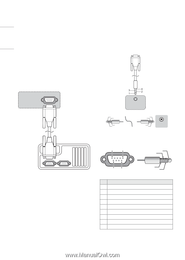
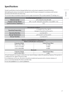
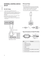
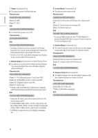
EXTERNAL CONTROL DEVICE SETUP, RS-232C Setup, Phone jack Type, Type of Connector: D-Sub 9-Pin Male
 |
View all LG 43UR640S manuals
Add to My Manuals
Save this manual to your list of manuals |
Page 34 highlights
ENGLISH EXTERNAL CONTROL DEVICE SETUP (PC) RS-232C Setup •• Image shown may differ from your TV. (PC) Connect the RS-232C (serial port) input jack to an external control device (such as a computer or an A/V control system) to control the product's functions externally. Connect the serial port of the control device to the RS-232C jack on the product back panel. •• RS-232C connection cables are not supplied with the product. (PC) RS-232C IN (CONTROL & SERVICE) (PC) (*Not Provided) USB IN USB IN Phone jack Type (Depending on model) •• You need to purchase the phone-jack to RS-232C cable required for the connection between the PC and the TV, which is specified in the manual. * For other models, connect to the USB port. * The connection interface may differ from your TV. RS-2 (PC) (PC) (CONTROL (TV) (PC) RS-232C IN (CONTROL & SERVICE) (TV) SERVICE ONLY SERVICE ONLY 1 3 13 (PC) (TV) 2 (PC) 13 (STB) 24 31 RS-232C IN (CONTROL & SERVICE) 42 (TV) 31 42 2 RS-232C IN (CONTROL & SERVICE) 31 RS-232C IN (CONTROL & SERVICE) 42 (TV) ((TTVV)) RS-23 (CONTROL Type of Connector: D-Sub 9-Pin Male RS-232C IN (CONTROL & SERVICE) (STB) (Depending on model) 13 24 1 5 69 (TXD) 1 (IR-OUT) 3 (GND) 4 (RXD) 2 RS-23 (CONTROL No. Pin name 1 3.5 V 2 RXD (Receive data) 3 TXD (Transmit data) RS-232C IN (CONTROL & SERVICE) 4 IR OUT from TV 5 GND 6 No Connection 7 No Connection (5 V available in some models) 8 No Connection 9 No Connection (12 V available in some models) 26
-
 1
1 -
2
-
3
-
4
-
5
-
6
-
7
-
8
-
9
-
10
-
11
-
12
-
13
-
14
-
15
-
16
-
17
-
18
-
19
-
20
-
21
-
22
-
23
-
24
-
25
-
26
-
27
-
28
-
 29
29 -
 30
30 -
 31
31 -
 32
32 -
 33
33 -
 34
34 -
 35
35 -
 36
36 -
 37
37 -
 38
38 -
 39
39 -
40
-
41
-
42
-
43
-
44
-
45
-
46
-
47
-
48
-
49
-
50
-
51
-
52
 |
 |