LG 50PJ340 Training Manual - Page 42
SMPS Connector P813 Identification, Voltages and Diode Check - tv model
 |
View all LG 50PJ340 manuals
Add to My Manuals
Save this manual to your list of manuals |
Page 42 highlights
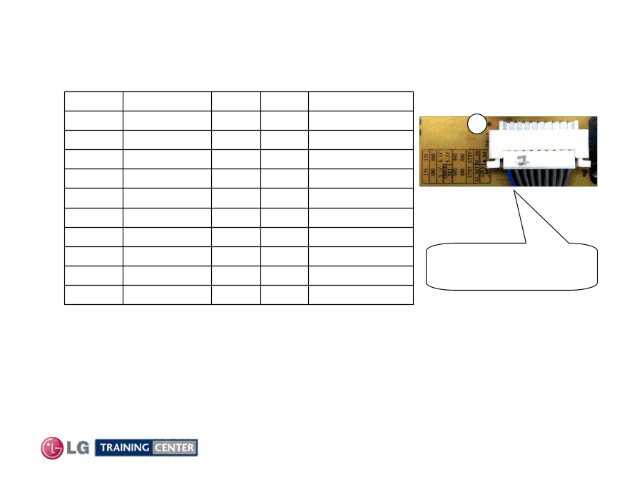
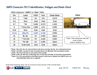
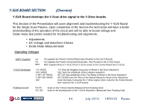
SMPS Connector P813 Identification, Voltages and Diode Check P813 Connector "SMPS" to "Main" P301 Pin Label STBY Run 1-2 a 16V 0V 17V 3-4 Gnd Gnd Gnd 5-7 a 5V 0.46V 5.17V 8 a c Error Det 2.85V 4.1V 9-12 Gnd Gnd Gnd 13-14 Stby 5V 3.46V 5.14V 15 RL On 0V 2.43V 16 a d AC Det 0V 4.44V 17 b M_ON 0V 3.29V 18 e Auto Gnd Gnd Gnd Diode Mode 3.17V Gnd 1.16V 3.09V Gnd 2.55V Open 3.06V Open Open P813 1 Note: This connector has two rows of pins. Odd on bottom row. a Note: The 17V, 5V, AC_Det and Error Det turn on when the RL_On command arrives. b Note: The M5V, Va and Vs turn on when the M_On (Monitor On) command arrives. c Note: The Error Det line is not used in this model. d Note: If the AC Det line is Missing, the TV will shut off after 10 seconds of operation. e Note: Pin 18 is grounded on the Main board. If this line is floated, the SMPS turns on Automatically when AC is applied. Diode Mode Readings taken with all connectors Disconnected. DVM in Diode Mode. 42 July 2010 50PJ350 Plasma
-
 1
1 -
2
-
3
-
4
-
5
-
6
-
7
-
8
-
9
-
10
-
11
-
12
-
13
-
14
-
15
-
16
-
17
-
18
-
19
-
20
-
21
-
22
-
23
-
24
-
25
-
26
-
27
-
28
-
29
-
30
-
31
-
32
-
33
-
34
-
35
-
36
-
 37
37 -
 38
38 -
 39
39 -
 40
40 -
 41
41 -
 42
42 -
 43
43 -
 44
44 -
 45
45 -
 46
46 -
 47
47 -
48
-
49
-
50
-
51
-
52
-
53
-
54
-
55
-
56
-
57
-
58
-
59
-
60
-
61
-
62
-
63
-
64
-
65
-
66
-
67
-
68
-
69
-
70
-
71
-
72
-
73
-
74
-
75
-
76
-
77
-
78
-
79
-
80
-
81
-
82
-
83
-
84
-
85
-
86
-
87
-
88
-
89
-
90
-
91
-
92
-
93
-
94
-
95
-
96
-
97
-
98
-
99
-
100
-
101
-
102
-
103
-
104
-
105
-
106
-
107
-
108
-
109
-
110
-
111
-
112
-
113
-
114
-
115
-
116
-
117
-
118
-
119
-
120
-
121
-
122
-
123
-
124
-
125
-
126
-
127
-
128
-
129
-
130
-
131
-
132
-
133
 |
 |