LG 60PV250 Owner's Manual - Page 9
Preparation, Accessories - owners manual
 |
View all LG 60PV250 manuals
Add to My Manuals
Save this manual to your list of manuals |
Page 9 highlights
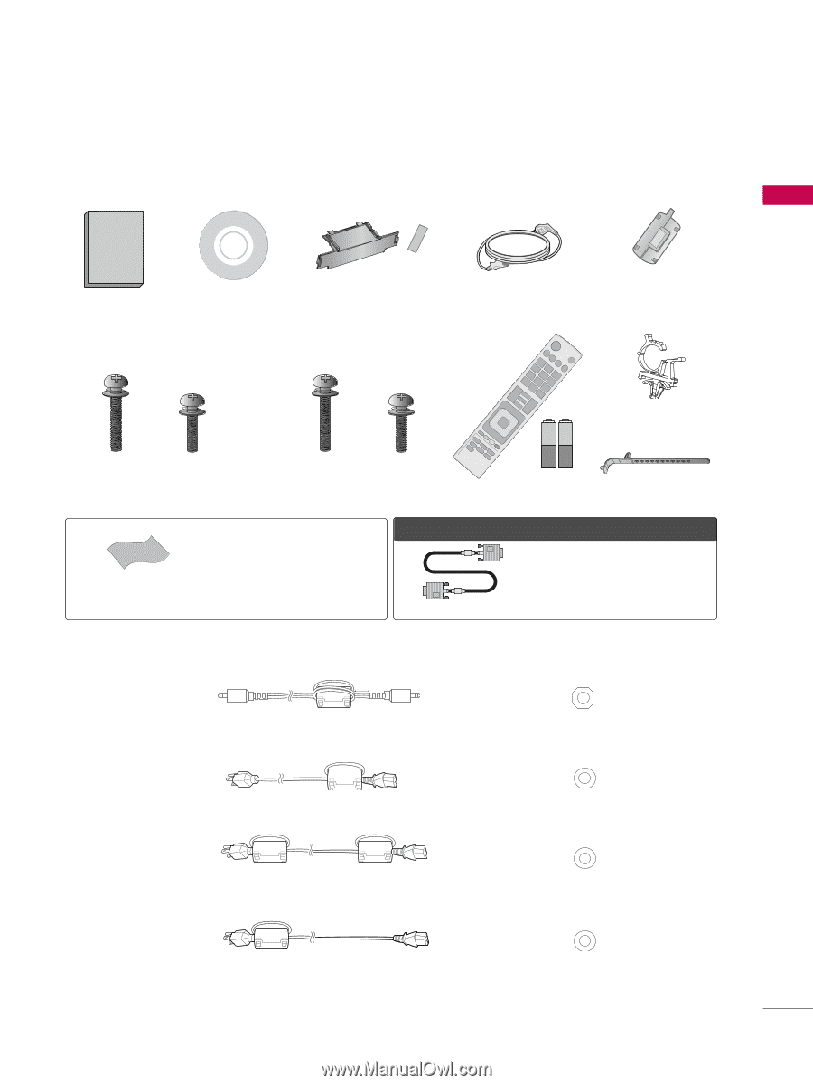
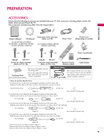
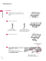
PREPARATION ACCESSORIES Ensure that the following accessories are included with your TV. If an accessory is missing, please contact the dealer where you purchased the TV. The accessories included may differ from the images below. PREPARATION Owner's Manual CD Manual (For 42/50PT200, 42/50PT350, 42/50PT350C, 42/50PT250U, 50PV400, 50PV450, 50PV450C, 50PV550U) Protection Cover and Tape (Refer to P.14) (For 60PV250, 60PV400, 60PV450, 60PV450C, 60PV550U) Power Cord Ferrite Core (Depending on model) x 4 x 3 x 4 x 3 1.5V 1.5V Power Cord Holder M4x26 M5x14.5 Screws for stand assembly (Refer to P.13, 14) M4x28 M5x24 Screws for stand assembly (Refer to P.13, 14) Remote Control, Batteries (AAA) Cable Holder * Wipe spots on the exterior only with the polishing cloth. * Do not wipe roughly when removing Polishing Cloth spots. Excessive pressure may cause scratch or discoloration. (Not included with all models) Option Extras When using the VGA (D-sub 15 pin cable) PC connection, the user must use shielded signal interface cables with ferrite cores to D-sub 15 pin Cable maintain standards compliance. I How to use the Ferrite Core 1. Use the ferrite core to reduce the electromagnetic interference in the PC audio cable. Wind the PC audio cable on the ferrite core thrice. Place the ferrite core close to the TV. [to an External device] 10 mm (+/-5 mm) [to the TV] [Figure 1] [Cross Section of Ferrite Core] 2. Use the ferrite core to reduce the electromagnetic interference in the power cable. Wind the power cable on the ferrite core once. Place the ferrite core close to the TV. [to a wall plug] [to the TV] [Figure 2] [Cross Section of Ferrite Core] 3. Use the ferrite core to reduce the electromagnetic interference in the power cable. Wind the power cable on the ferrite core once. Place the ferrite core close to the TV and a wall plug. [to a wall plug] [to the TV] [Figure 3] [Cross Section of Ferrite Core] 4. Use the ferrite core to reduce the electromagnetic interference in the power cable. Wind the power cable on the ferrite core once. Place the ferrite core close to a wall plug. [to a wall plug] [to the TV] [Figure 4] - If there is one ferrite core, follow as shown in Figure 4. - If there are two ferrite cores, follow as shown in Figures 1 and 2. - If there are three ferrite cores, follow as shown in Figures 1 and 3. [Cross Section of Ferrite Core] 9
-
 1
1 -
2
-
3
-
 4
4 -
 5
5 -
 6
6 -
 7
7 -
 8
8 -
 9
9 -
 10
10 -
 11
11 -
 12
12 -
 13
13 -
 14
14 -
15
-
16
-
17
-
18
-
19
-
20
-
21
-
22
-
23
-
24
-
25
-
26
-
27
-
28
-
29
-
30
-
31
-
32
-
33
-
34
-
35
-
36
-
37
-
38
-
39
-
40
-
41
-
42
-
43
-
44
-
45
-
46
-
47
-
48
-
49
-
50
-
51
-
52
-
53
-
54
-
55
-
56
-
57
-
58
-
59
-
60
-
61
-
62
-
63
-
64
-
65
-
66
-
67
-
68
-
69
-
70
-
71
-
72
-
73
-
74
-
75
-
76
-
77
-
78
-
79
-
80
-
81
-
82
-
83
-
84
-
85
-
86
-
87
-
88
-
89
-
90
-
91
-
92
-
93
-
94
-
95
-
96
-
97
-
98
-
99
-
100
-
101
-
102
-
103
-
104
-
105
-
106
-
107
-
108
-
109
-
110
-
111
-
112
-
113
-
114
-
115
-
116
-
117
-
118
-
119
-
120
-
121
-
122
-
123
-
124
 |
 |