LG B2050 Service Manual - Page 18
B. Opll
 |
View all LG B2050 manuals
Add to My Manuals
Save this manual to your list of manuals |
Page 18 highlights
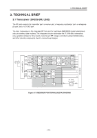
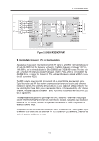
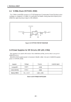
3. TECHNICAL BRIEF B. OPLL The OPLL consists of a feedback mixer, a phase detector, a loop filter, and a fully integrated TXVCO. The TXVCO is centered between the DCS 1800 and PCS 1900 bands, and its output is divided by 2 for the GSM 850 and E-GSM 900 bands. The RFLO frequency is generated between 1272 and 1483 MHz. To allow a single VCO to be used for the RFLO, high-side injection is used for the GSM 850 and E-GSM 900 bands, and low-side injection is used for the DCS 1800 and PCS 1900 bands. The I and Q signals are automatically swapped when switching bands. Additionally, the SWAP bit in register 03h can be used to manually exchange the I and Qsignals. Low-pass filters before the OPLL phase detector reduce the harmonic content of the quadraturemodulator and feedback mixer outputs. The cutoff frequency of the filters is programmable with the FIF[3:0] bits in register 04h (Figure 3-3), and should be set to the recommended settings detailed in the register description. - 17 -
-
 1
1 -
2
-
3
-
4
-
5
-
6
-
7
-
8
-
9
-
10
-
11
-
12
-
 13
13 -
 14
14 -
 15
15 -
 16
16 -
 17
17 -
 18
18 -
 19
19 -
 20
20 -
 21
21 -
 22
22 -
 23
23 -
24
-
25
-
26
-
27
-
28
-
29
-
30
-
31
-
32
-
33
-
34
-
35
-
36
-
37
-
38
-
39
-
40
-
41
-
42
-
43
-
44
-
45
-
46
-
47
-
48
-
49
-
50
-
51
-
52
-
53
-
54
-
55
-
56
-
57
-
58
-
59
-
60
-
61
-
62
-
63
-
64
-
65
-
66
-
67
-
68
-
69
-
70
-
71
-
72
-
73
-
74
-
75
-
76
-
77
-
78
-
79
-
80
-
81
-
82
-
83
-
84
-
85
-
86
-
87
-
88
-
89
-
90
-
91
-
92
-
93
-
94
-
95
-
96
-
97
-
98
-
99
-
100
-
101
-
102
-
103
-
104
-
105
-
106
-
107
-
108
-
109
-
110
-
111
-
112
-
113
-
114
-
115
-
116
-
117
-
118
-
119
-
120
-
121
-
122
-
123
-
124
-
125
-
126
-
127
-
128
-
129
-
130
-
131
-
132
-
133
 |
 |