LG DLE2140W Owner's Manual - Page 21
Four-Wire Connection for Electric Dryers: Direct Wire, USA ONLY
 |
UPC - 048231011402
View all LG DLE2140W manuals
Add to My Manuals
Save this manual to your list of manuals |
Page 21 highlights
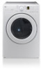
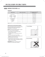
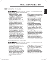
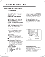
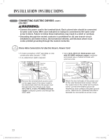
ENGLISH CONNECTING ELECTRIC DRYERS (cont.) USA ONLY wWARNING: • Connect the power cord to the terminal block. Each colored wire should be connected to same color screw. Wire color indicated on manual is connected to the same color screw in block. Failure to follow these instructions may result in a short or overload. • Grounding through the neutral conductor is prohibited for: (1) new branch-circuit installations, (2) mobile homes, (3) recreational vehicles, and (4) areas where local codes prohibit grounding through the neutral conductor. Four-Wire Connection for Electric Dryers: Direct Wire • A 4-wire connection is required for all mobile and manufactured home installations, as well as all new construction after January 1, 1996. • A UL-listed strain relief is required. • Use UL-listed 4-wire #10 AWG-minimum copper conductor cable. • Allow at least 5 ft. (1.5 m) length to allow for removal and reinstallation of the dryer. 1" (2.5 cm) 5" (12.7 cm) Ground Wire 1 Remove 5 inches (12.7 cm) of the outer covering from the wire. Remove 5 inches of insulation from the ground wire. Cut off approximately 11⁄2 inches (3.8 cm) from the other three wires and strip 1 inch (2.5 cm) insulation from each wire. Bend the ends of the three shorter wires into a hook shape. Terminal Block UL-Listed Strain Relief Hot Neutral Hot (Black) (White) (Red) Ground Screw Neutral Grounding wire Ground Wire 3 Transfer the dryer's ground wire from behind the green ground screw to the center screw of the terminal block. Attach the two hot leads of the power cable to the outer terminal block screws. Attach the white neutral wire to the center terminal block screw. Attach the power cable ground wire to the green ground screw. Tighten all screws securely. Reinstall the terminal block access cover. UL-Listed 4-Wire Power Cord 2 Remove the terminal block access cover on the upper back of the dryer. Install a UL-listed strain relief into the power cord through-hole; then thread the power cable prepared in Step 1 through the strain relief. MFL62512832_EN_100720.indd 21 21 7/21/10 1:55:51 PM
-
 1
1 -
2
-
3
-
4
-
5
-
6
-
7
-
8
-
9
-
10
-
11
-
12
-
13
-
14
-
15
-
 16
16 -
 17
17 -
 18
18 -
 19
19 -
 20
20 -
 21
21 -
 22
22 -
 23
23 -
 24
24 -
 25
25 -
 26
26 -
27
-
28
-
29
-
30
-
31
-
32
-
33
-
34
-
35
-
36
-
37
-
38
-
39
-
40
-
41
-
42
-
43
-
44
-
45
-
46
-
47
-
48
-
49
-
50
-
51
-
52
-
53
-
54
-
55
-
56
-
57
-
58
-
59
-
60
-
61
-
62
-
63
-
64
-
65
-
66
-
67
-
68
-
69
-
70
-
71
-
72
-
73
-
74
-
75
-
76
-
77
-
78
-
79
-
80
-
81
-
82
-
83
-
84
-
85
-
86
-
87
-
88
-
89
-
90
-
91
-
92
-
93
-
94
-
95
-
96
-
97
-
98
-
99
-
100
-
101
-
102
-
103
-
104
-
105
-
106
-
107
-
108
-
109
-
110
-
111
-
112
-
113
-
114
-
115
-
116
-
117
-
118
-
119
-
120
-
121
-
122
-
123
-
124
 |
 |