LG DLE5977W Owners Manual - Page 18
Option 2, wire connection with a, Power supply cord. - how to remove front
 |
View all LG DLE5977W manuals
Add to My Manuals
Save this manual to your list of manuals |
Page 18 highlights
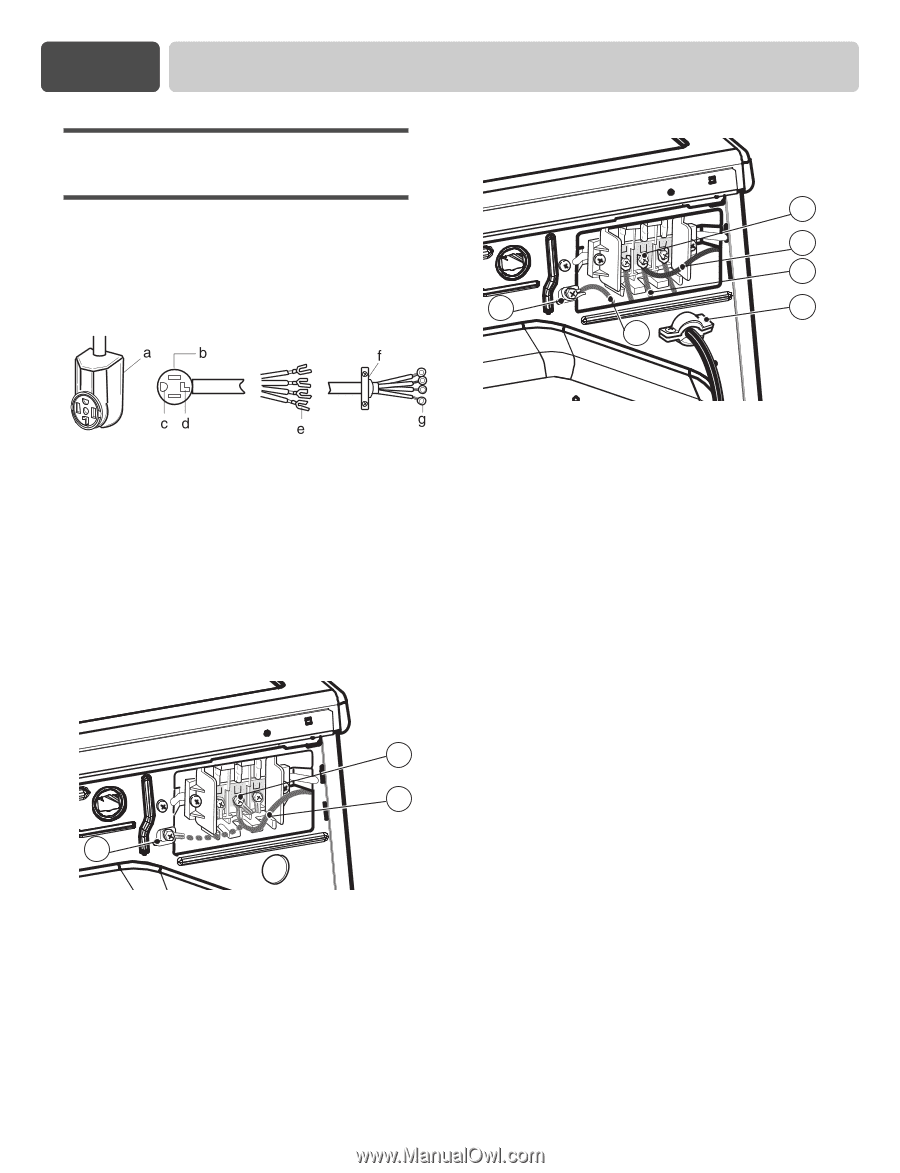
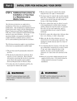
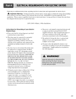
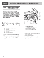
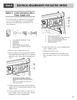
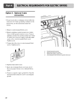
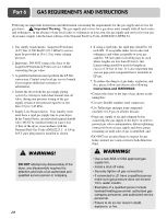
Part 4 ELECTRICAL REQUIREMENTS FOR ELECTRIC DRYERS Option 2: 4-wire connection with a Power supply cord. d • lf your local codes or ordinances do not allow the use of a 3 wire connection, or you are installing e your dryer in a mobile home, you must use a 4wire connection. f a c b a. 4-wire receptable (NEMA type 14-30R) b. 4-pront plug c. Ground prong d. Neutral Prong e. Spade terminals with upturned ends f. 3/4 in. (1.9 cm) UL approved strain relief g. Ring terminals 1. Remove center terminal block screw. 2. Remove appliance neutral ground wire (white) from external ground connector screw. Fasten it under the center, silver colored terminal block screw. b c a a. External ground connector - Dotted line shows position of NEUTRAL ground wire before being moved to center terminal block screw b. Center silver-colored terminal block screw c. White wire of harness 3. Connect ground wire (green or bare) of power supply cable to external ground conductor screw. Tighten screw. 4. Connect neutral wire (white or center wire) of power supply cord to the center, silver colored terminal screw of the terminal block. a. External ground connector b. Green or bare copper wire of power supply cord c. 3/4 in. (1.9 cm) UL-listed strain relief d. Center silver-colored terminal block screw e. Neutral grounding wire (white) f. Neutral wire (white) 5. Connect the other wires to outer terminal block screws. Tighten screws. 6. Tighten strain relief screws. 7. Insert tab of terminal block cover into slot of dryer rear panel. Secure cover with hold-down screw. 17
-
 1
1 -
2
-
3
-
4
-
5
-
6
-
7
-
8
-
9
-
10
-
11
-
12
-
 13
13 -
 14
14 -
 15
15 -
 16
16 -
 17
17 -
 18
18 -
 19
19 -
 20
20 -
 21
21 -
 22
22 -
 23
23 -
24
-
25
-
26
-
27
-
28
-
29
-
30
-
31
-
32
-
33
 |
 |