LG DLEX7600VE Owners Manual - Page 31
Final Installation Check
 |
View all LG DLEX7600VE manuals
Add to My Manuals
Save this manual to your list of manuals |
Page 31 highlights
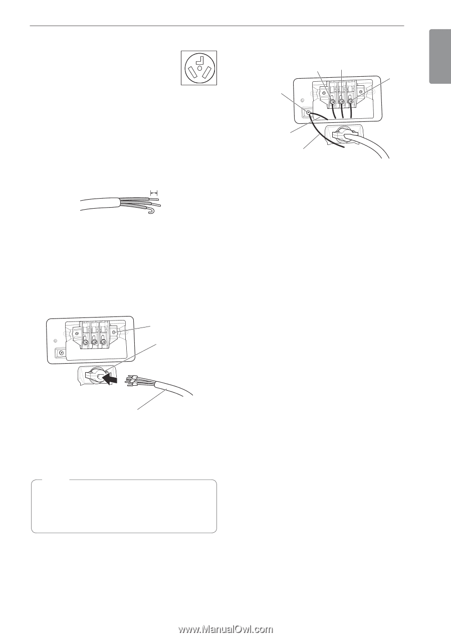
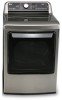
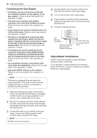
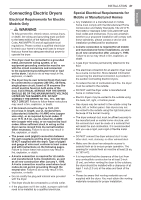
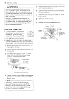
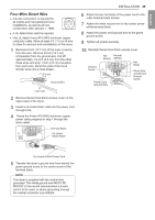
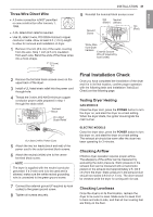
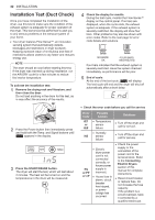
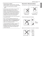
ENGLISH Three-Wire Direct Wire •• A 3-wire connection is NOT permitted on new construction after January 1, 1996. •• A UL-listed strain relief is required. •• Use UL-listed 3-wire, #10 AWG-minimum copper conductor cable. Allow at least 5 ft. (1.5 m) length to allow for removal and installation of dryer. 1 Remove 3½-inch (8.9 cm) of the outer covering from the wire. Strip 1 inch (2.5 cm) insulation from each wire. Bend the ends of the three wires into a hook shape. 1" (2.5 cm) INSTALLATION 31 9 Reinstall the terminal block access cover. Hot Neutral (Black) (White) Ground Screw Hot (Red) White Wire from Dryer harness External Ground Wire (If required by local codes) 2 Remove the terminal block access cover on the upper back of the dryer. 3 Install a UL-listed strain relief into the power cord through-hole. 4 Thread the 3-wire, #10 AWG-minimum copper conductor power cable prepared in step 1 through the strain relief. Terminal Block UL-Listed Strain Relief UL-Listed 3-Wire Power Cord 5 Attach the two hot leads (black and red) of the power cord to the outer terminal block screws. 6 Attach the neutral (white) wire to the center terminal block screw. NOTE The dryer is supplied with the neutral conductor grounded. If a 3-wire cord is to be used and is allowed, make sure the white neutral grounding wire is connected to the green ground screw. 7 Connect the external ground (if required by local codes) to the green ground screw. 8 Tighten all screws securely. Final Installation Check Once you have completed the installation of the dryer and it is in its final location, confirm proper operation with the following tests and Installation Test (Duct Check) on the following page. Testing Dryer Heating GAS MODELS Close the dryer door, press the POWER button to turn the dryer on, and start the dryer on a heat setting. When the dryer starts, the igniter should ignite the main burner. ELECTRIC MODELS Close the dryer door, press the POWER button to turn the dryer on, and start the dryer on a heat setting. The exhaust air should be warm after the dryer has been operating for 3 minutes. Checking Airflow Effective dryer operation requires proper airflow. The adequacy of the airflow can be measured by evaluating the static pressure. Static pressure in the exhaust duct can be measured with a manometer, placed on the exhaust duct approximately 2 ft. (60.9 cm) from the dryer. Static pressure in the exhaust duct should not exceed 0.6-inch (1.5 cm). The dryer should be checked while the dryer is running with no load. Checking Levelness Once the dryer is in its final location, recheck the dryer to be sure it is level. Make sure it is level front to back and side to side, and that all four leveling feet are firmly on the floor.
-
 1
1 -
2
-
3
-
4
-
5
-
6
-
7
-
8
-
9
-
10
-
11
-
12
-
13
-
14
-
15
-
16
-
17
-
18
-
19
-
20
-
21
-
22
-
23
-
24
-
25
-
 26
26 -
 27
27 -
 28
28 -
 29
29 -
 30
30 -
 31
31 -
 32
32 -
 33
33 -
 34
34 -
 35
35 -
 36
36 -
37
-
38
-
39
-
40
-
41
-
42
-
43
-
44
-
45
-
46
-
47
-
48
-
49
-
50
-
51
-
52
-
53
-
54
-
55
-
56
-
57
-
58
-
59
-
60
-
61
-
62
-
63
-
64
-
65
-
66
-
67
-
68
-
69
-
70
-
71
-
72
-
73
-
74
-
75
-
76
-
77
-
78
-
79
-
80
-
81
-
82
-
83
-
84
-
85
-
86
-
87
-
88
-
89
-
90
-
91
-
92
-
93
-
94
-
95
-
96
-
97
-
98
-
99
-
100
-
101
-
102
-
103
-
104
-
105
-
106
-
107
-
108
-
109
-
110
-
111
-
112
-
113
-
114
-
115
-
116
-
117
-
118
-
119
-
120
-
121
-
122
-
123
-
124
-
125
-
126
-
127
-
128
-
129
-
130
-
131
-
132
 |
 |