LG DLG2522W Service Manual
LG DLG2522W Manual
 |
View all LG DLG2522W manuals
Add to My Manuals
Save this manual to your list of manuals |
LG DLG2522W manual content summary:
- LG DLG2522W | Service Manual - Page 1
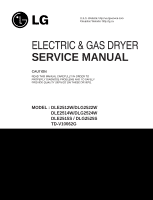
: http://us.lgservice.com Canadian Website: http://lg.ca ELECTRIC & GAS DRYER SERVICE MANUAL CAUTION READ THIS MANUAL CAREFULLY IN ORDER TO PROPERLY DIAGNOSE PROBLEMS AND TO SAFELY PROVIDE QUALITY SERVICE ON THESE DRYERS. MODEL : DLE2512W/DLG2522W DLE2514W/DLG2524W DLE2515S / DLG2525S TD-V10062G - LG DLG2522W | Service Manual - Page 2
Apr. 2004 PRINTED IN KOREA P/No.:3828EL3005B - LG DLG2522W | Service Manual - Page 3
necessary checks. RECONNECT ALL GROUNDING DEVICES If grounding wires, screws, straps, clips, nuts, or washers used to complete a path to ground are removed for service, they must be returned to their original position and properly fastened. WHAT TO DO IF YOU SMELL GAS: Do not try to light a match - LG DLG2522W | Service Manual - Page 4
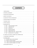
GAS SETTING (NATURAL GAS, PROPANE GAS 28 11. DISASSEMBLY INSTRUCTIONS 30 12. EXPLODED VIEW ...37 12-1. CONTROL PANEL & PLATE ASSEMBLY 37 12-2. CABINET & DOOR ASSEMBLY 38 12-3-1. DRUM & MOTOR ASSEMBLY: ELECTRIC MODEL 39 12-3-2. DRUM & MOTOR ASSEMBLY: GAS MODEL 40 13. REPLACEMENT PARTS LIST - LG DLG2522W | Service Manual - Page 5
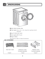
I Name: Electric and Gas Dryer I Power supply: Please refer to the rating label regarding detailed information. I Size: 27 X 29.6 X 38.7 (inch) I Dryer capacity: IEC 7.0 cu.ft. I Weight: 126(Ibs) Specifications are subject to change by manufacturer. I ACCESSORIES Dryer rack (1 each) See - LG DLG2522W | Service Manual - Page 6
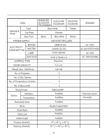
MODEL) AC 120V GAS VALVE CONTROL TYPE 13 W (110mA) x 2 Electronic AC 120V (GAS MODEL) DRUM CAPACITY 7.0 cu.ft. Weight (lbs) - Net/Gross 124/144 No. of Programs 5 No. of Dry Options 3 No. of Temperature Controls 5 No. of Dry Levels 3 Sound levels High/Low/Off Sensor Moisture - LG DLG2522W | Service Manual - Page 7
2 FEATURES AND BENEFITS 3 INSTALLATION INSTRUCTIONS Dryer Rack Installation Instructions 1Open the door. Hold the dryer rack with both hands. 2 Put the dryer rack into the drum 3 Check and be sure that the front of the rack is properly seated behind the lint filter. 6 - LG DLG2522W | Service Manual - Page 8
washer and dryer. Slide the dryer back against the stop on the side rail. 1 2 Stacking kit Place the washer firmly on a stable, even and solid floor as product installation instructions describe in the owner's manual kit with a gas dryer in potentially unstable conditions like a mobile home. 7 - LG DLG2522W | Service Manual - Page 9
Pedestal Installation Instructions For washer, dryer, and combo LG 27" 4 side first. 1 Remove pedestal, installation hardware, and instructions from the shipping carton. 2 Position the dryer on top of the pedestal. , for washer/ combo for dryer 5 Be sure to press the adhesive parts of the brackets - LG DLG2522W | Service Manual - Page 10
Dryer Only Review the following options to determine the appropriate electrical connection for your home: 4-wire receptacle (NEMA type14-30R) Use the instructions under option 1 if your home homehas a 4-wire receptacle (NEMA type 14-30R). 3-wire receptacle (NEMA type10-30R) Use the instructions - LG DLG2522W | Service Manual - Page 11
) of length in order for cm) dryer to be 31/2" (8.6 cm) replaced. First, peel 3 1/2 inch (8.9cm codes or ordinances do not allow the use of a 3 wire connection, or you are installing your dryer the power cord to the external ground screw. Remove the neutral ground wire of appliance and connect - LG DLG2522W | Service Manual - Page 12
the instructions under Section 3: Optional 3-wire connection. Option 3: Optional 3-wire connection. • If your local codes or Tighten the strain relief screws (C) securely. A B C 11 1. Remove the appliance ground wire (D) (green) fromthe external ground connector screw service or cleaning.) - LG DLG2522W | Service Manual - Page 13
Stainless Steel Flexible Connector - Use only if allowed by local codes (Use Design A.G.A. Certified Connector) 2 1/8" N.P.T. Pipe Plug (for checking inlet gas pressure) 3 Equipment Shut-Off Valve-Installed within 6' (1.8 m) of dryer 4 Black Iron Pipe Shorter than 20' (6.1 m) - Use 3/8" pipe Longer - LG DLG2522W | Service Manual - Page 14
4 DRYER CYCLE PROCESS Default Conditions of operation and termination Cycle Drying Cooling Wrinkle care Temp- Dry Display erature ) 38±5°C SPEED DRY (HIGH) - 25min Saturation (70±5°C) (5min) (47±5°C) Manual 3Hr Dry ** AIR DRY - - 30min Saturation No heater N/A N/A Motor Off - LG DLG2522W | Service Manual - Page 15
cut off • Check Top Marking: N130 2. Hi limit Thermostat (Auto reset) 3. Outlet Thermostat ( Auto reset) • Check Top Marking: N85 4. Lamp holder Test Procedure Check result Remark Measure resistance of terminal If thermal fuse is open must • Heater case- to terminal be replaced Safety Open - LG DLG2522W | Service Manual - Page 16
COM) - 2 Terminal: 1 (COM) - 3 Terminal: 2 - 3 Check result Resistance value: 10Ω Resistance value: 10Ω Resistance value: 20Ω Remark • valve 2 Measure resistance of terminal to terminal Resistance value: 100~800Ω • Gas type 12. Frame Detect Measure resistance of terminal to terminal Open at 370 - LG DLG2522W | Service Manual - Page 17
at 158 ± 9°F (70 ± 5°C) Check result Resistance value ∞ Continuity < 1Ω Remark • Gas type • Gas funnel Measure resistance of terminal to terminal Open at 212 ± 12°F (100 ± 7°C) Manual reset If thermal fuse is open must be replaced Resistance value ∞ Continuity < 1Ω • Gas type • Gas funnel 16 - LG DLG2522W | Service Manual - Page 18
6 MOTOR DIAGRAM AND SCHEMATIC NOTE When checking Component, be sure to turn Power off, then do voltage discharge sufficiently. Contact On / Off by Centrifugal Switch STOP MODE (When Motor does not operate) RUN MODE (Motor operates) Centrifugal switch Centrifugal switch (Pull Drive forward) 17 - LG DLG2522W | Service Manual - Page 19
7 CONTROL LAY - OUT PWB ASSEMBLY DISPLAY LAY-OUT Option part MODEL DISPLAY AS DIAGNOSTIC TEST MODEL DLE2512W DLE2514W DLE2515S DLG2522W DLG2524W DLG2525S TD-V10062G DP 1 X X X PWB ASSEMBLY LAY-OUT OPTION PART DP 3 X O O OP 5 X X X LED DISPLAY P/No 18:HO 6871EC1120A 19:HO 6871EC1120B 19:HO - LG DLG2522W | Service Manual - Page 20
8 WIRING DIAGRAM ELECTRIC DRYER WIRING DIAGRAM GAS DRYER WIRING DIAGRAM 19 - LG DLG2522W | Service Manual - Page 21
1. This TEST should be used for Factory test /Service test. Do not use this DIAGNOSTIC TEST other than specified. 2. Activating the Heater manually with the Door open may trip the Thermostat attached to the Heater, therefore do not activate it manually. (Do not press the door switch to operate the - LG DLG2522W | Service Manual - Page 22
When measuring power, be sure to wear insulated gloves, to and avoid an electric shock. Trouble Symptom No power was applied to Controller. (LED, Display off) Measurement Condition With Dryer Power On; Connector linked to Controller. Check the outlet, is the voltage 110V ~ 125V AC? YES NO - LG DLG2522W | Service Manual - Page 23
discharging, contact the metal plug of Power cord with the Ground.) Trouble Symptom During Diagnostic Test, tE1 and tE2 Error occur. During operation, to Controller. YES • Check if Control and the 6 pin connector are properly connected. • Replace Controller. NO Check if resistance is in the - LG DLG2522W | Service Manual - Page 24
NO YES • Replace Control. (Relay check) • Check Controller connector. • Replace Outlet • Thermostat. (Refer to 'Component') • Check Idler Assembly. • Drum Belt cuts off • Drum Belt takes off from • Motor Pulley. • Replace Idler Switch. • Check Motor. (Refer to 'Motor Diagram & Check') • Check if - LG DLG2522W | Service Manual - Page 25
measuring the voltage in the 6 pin connector's Pin (BLUE wire) and Pin (ORANGE wire)? YES • Replace Control and Check. Normal Condition Table 2. IMC Ratio and Display Value / Voltage (IMC: Initial Moisture Content) IMC 70% ~ 40% 40% ~ 20% Display Value Voltage (DC) (between 6 Pin terminal 50 - LG DLG2522W | Service Manual - Page 26
opening Door, Drum motor and Trouble Symptom Heater run continuously; Door Close is not sensed. (Drum motor will not operate. Display will flash at 0.5 second intervals.) Measurement Condition After turning Dryer Power Off, measure resistance. Measure while Door is closed. Check if resistance is - LG DLG2522W | Service Manual - Page 27
with earth line.) Trouble Symptom While operating, Heating will not work. Thermostat). NO YES • Replace TH2 (Safety Thermostat). Check if the value of measured resistance is below 1Ω between terminal TH3 (HI-Limit Thermostat). NO YES • Replace TH3 (HI-Limit Thermostat). Check Motor. Check - LG DLG2522W | Service Manual - Page 28
electric shock. Trouble Symptom While operating, Heating will not work. Drying time takes longer. Measurement Condition With dryer power on Valve 1 Igniter Valve 2 Power On & Start (Normal Cycle) NO When measuring Valve 1 voltage, More than DC 90V? YES NO • Check thermostat Hi limit Safety - LG DLG2522W | Service Manual - Page 29
Gas Orifice is on sale as a Service Part to authorized servicers only. STEP 1 : VALVE SETTING Opened Closed Full open Adjustment screw STEP 2 : ORIFICE CHANGE Orifice Close Adjustment screw Remove 2 screws. Disassemble the pipe assembly. Replace Natural Gas orifice with Propane Gas orifice. Gas - LG DLG2522W | Service Manual - Page 30
IGNITER ON IGNITER NO TEMPERATURE ABOUT 370°F YES FLAME DETECT OPEN IGNITER OFF VALVE 2 ON GAS IGNITION YES DRYING NO FLAME DETECT CLOSE VALVE 2 OFF GAS IGNITION START VALVE 1 IGNITER FLAME DETECT VALVE 2 ON ON CLOSE OFF OFF OPEN ON GAS IGNITION GAS VALVE STRUCTURE Adjustment Screw 29 - LG DLG2522W | Service Manual - Page 31
11 DISASSEMBLY INSTRUCTIONS ✽ Disassemble and repair the unit only after pulling out power plug from the outlet. TOP PLATE ! WARNING ! When you disassemble the top plate, be sure to take gloves and careful plate's edge. Failure to do so can cause serious injury. 1. Remove 3 screws on the upper - LG DLG2522W | Service Manual - Page 32
! WARNING ! When you disassemble the control panel, be sure to take gloves and careful panel frame's edge. Failure to do so can cause serious injury. 1. Remove 2 screws on the control panel frame. 2. Disconnect the connectors. 3. Pull the control panel assembly upward and then forward - LG DLG2522W | Service Manual - Page 33
and careful cabinet edge. Failure to do so can cause serious injury. 1. Disassemble the top plate. 2. Disassemble the control panel assembly. 3. Disassemble the door assembly. 4. Remove 2 screws. 5. Remove 4 screws from the top of cabinet cover. 6. Disconnect the door switch harness. 32 - LG DLG2522W | Service Manual - Page 34
Cabinet Cover and Tub drum [front]. 3. Loosen belt from motor and idler pulleys. 4. Carefully remove the drum. CHANGING THE DRUM LAMP 1. Disassemble the door. 2. Hold the lamp shield in place while removing the screw. 3. Slide the shield up and remove. 4. Remove the bulb and replace with a 15 watt - LG DLG2522W | Service Manual - Page 35
duct. 2-1. Detach and remove a knockout at the botton, left or right side as desired. (Right Side Vent not available on Gas dryer the order of work. DUCT TAPE 2-2. Reconnect the another duct [11 in (28cm)] to the blower housing, and attach the duct to the base. (Duct is a SVC part) DUCT TAPE - LG DLG2522W | Service Manual - Page 36
Grid. 4. Disconnect the electrode sensor. 1. Disassemble the top plate. 2. Remove the Cabinet Cover and Tub Drum [Front]. 3. Remove the Drum assembly. 4. Remove 2 screws and cover (Air guide). 5. Remove the bolt and washer. 6. Remove the fan. 7. Disconnect the motor clamp and motor. 1. Disassemble - LG DLG2522W | Service Manual - Page 37
Remove the filter and 2 screws. 4. Remove the air duct. 1. Disassemble the top plate. 2. Remove the Cover Cabinet and Tub Drum [Front]. 3. Remove the Drum assembly and Tub Drum [Rear]. 4. Disconnect the Air duct from the Tub Drum [Front]. 5. Remove the roller from the Tub Drum [Front] and Tub Drum - LG DLG2522W | Service Manual - Page 38
12 EXPLODED VIEW 12-1. Control Panel & Plate Assembly A210 A120 A130 A110 37 - LG DLG2522W | Service Manual - Page 39
12-2. Cabinet & Door Assembly A390 A700 A800 A570 A560 A330 A320 A310 A600 A550 A500 A300 A400 A530 A525 A520 A540 A510 A460 A420 A410 A450 A430 38 - LG DLG2522W | Service Manual - Page 40
12-3-1. Drum & Motor Assembly: Electric Type F200 K400 K120 K100 K130 K221 K230 K210 K350 K140 K250 K251 K330 K320 K340 K250 K251 K360 K550 K560 K310 K620 K610 K240 F130 F110 F120 F140 K540 K510 K520 K530 K651 K640 K600 K650 39 - LG DLG2522W | Service Manual - Page 41
12-3-2. Drum & Motor Assembly: Gas type K120 F200 K400 K100 K130 K221 K230 K210 K350 K140 K250 K251 K330 K320 K340 K250 K251 K360 K550 K560 K310 K540 K510 K520 M160 M171 M170 M140 M110 M181 M190 M180 M230 M250 40 K530 K651 K640 K600 K650 M210 M171: Propane Gas orifice M170: Natural
-
 1
1 -
 2
2 -
 3
3 -
 4
4 -
 5
5 -
 6
6 -
 7
7 -
8
-
9
-
10
-
11
-
12
-
13
-
14
-
15
-
16
-
17
-
18
-
19
-
20
-
21
-
22
-
23
-
24
-
25
-
26
-
27
-
28
-
29
-
30
-
31
-
32
-
33
-
34
-
35
-
36
-
37
-
38
-
39
-
40
-
41
 |
 |

U.S.A. Website: http://us.lgservice.com
Canadian Website: http://lg.ca
ELECTRIC & GAS DRYER
SERVICE MANUAL
CAUTION
READ THIS MANUAL CAREFULLY IN ORDER TO
PROPERLY DIAGNOSE PROBLEMS AND TO SAFELY
PROVIDE QUALITY SERVICE ON THESE DRYERS.
MODEL : DLE2512W/DLG2522W
DLE2514W/DLG2524W
DLE2515S / DLG2525S
TD-V10062G