LG HMC036KDT1 Service Manual - Page 49
WARNING, Outdoor
 |
View all LG HMC036KDT1 manuals
Add to My Manuals
Save this manual to your list of manuals |
Page 49 highlights
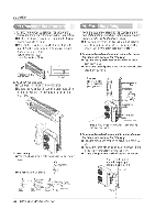
Connection of the cable 1. Remove the cover control from the unit by loosening the screw. A-UNIT B-UNIT C-UNIT LI L2 C G V S C VS C V S P▪ower Source 20E030V AG (High voltage) Connecung cable{Low voltage Outdoor unit Terminal block Over 5mm Holder for power supply cord Installation Power supply cable C V S Terminal BLOCK Indoor A-UNIT V S Terminal BLOCK Indoor B-UNIT V S Terminal BLOCK Indoor C-UNIT Cover control Connecting cable 2. Dismount caps on the conduit panel. 3. Temporarily mount the conduit tubes on the conduit panel. 4. Connect the wires to the terminals on the control board individually as the following. 5. Secure the cable onto the control board with the holder (damper). 6. Ground the unit in accordance with local codes. 7. Refix the cover control to the original position with the screw. 8. Use lock nuts to secure the conduit tubes. CAUTION The power cable connected to the outdoor unit should be complied with the following specifications. (UL recognized and GSA certified) AWG 12 NOTE 1. Separately wire the high and low voltage line. 2. Use heat-proof electrical wiring capable of withstanding temperature up to 167°F. 3. Use outdoor and waterproof connection cable rated more than 300V for the connection between indoor and outdoor unit. (For example, Type SJO-WA) /N. WARNING • Be sure to comply with local codes while running the wire from the indoor unit to the outdoor unit(size of wire and wiring method, etc). • Every wire must be connected firmly. • No wire should be allowed to touch refrigerant tubing, the compressor or any moving parts. /?) The connecting cable connected to the indoor and outdoor unit should be complied with the following specifications. (UL recognized and CSA certified) AWG 18 Service Manual 49
-
 1
1 -
2
-
3
-
4
-
5
-
6
-
7
-
8
-
9
-
10
-
11
-
12
-
13
-
14
-
15
-
16
-
17
-
18
-
19
-
20
-
21
-
22
-
23
-
24
-
25
-
26
-
27
-
28
-
29
-
30
-
31
-
32
-
33
-
34
-
35
-
36
-
37
-
38
-
39
-
40
-
41
-
42
-
43
-
 44
44 -
 45
45 -
 46
46 -
 47
47 -
 48
48 -
 49
49 -
 50
50 -
 51
51 -
 52
52 -
 53
53 -
 54
54 -
55
-
56
-
57
-
58
-
59
-
60
-
61
-
62
-
63
-
64
-
65
-
66
 |
 |
