LG KE990 Service Manual - Page 14
Technical Brief - ke990c
 |
View all LG KE990 manuals
Add to My Manuals
Save this manual to your list of manuals |
Page 14 highlights
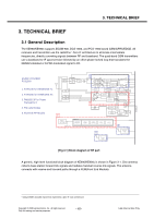
3. TECHNICAL BRIEF 3. TECHNICAL BRIEF 3.1 General Description The KE990/KE990c supports EGSM-900, DCS-1800, and PCS-1900 based GSM/GPRS/EDGE. All receivers and transmitter use the radioOne 1 Zero-IF architecture to eliminate intermediate frequencies, directly converting signals between RF and baseband. The quad-band GSM transmitters use a baseband-to-IF upconversion followed by an offset phase-locked loop that translates the GMSKmodulated or 8-PSK-modulated signal to RF. ESM6270 EGSM / DCS1800/ PCS1900 1. RTR6235 for GSM/EDGE Tx 2. RTR6235 for GSM/EDGE Rx 3. PM6635-3P for Power Management 4. FM radio Module 5. Bluetooth RF Module SW pad pad H-BPF L-BPF GSM/EDGE PA G 900 Tx BPF GSM850 Rx BPF GSM1800 Rx BPF GSM1900 Rx BPF 3 1 BPF BPF BPF BPF Pow er Detector Quadrature Upconverter Quadrature U pc onv ert er LPF DAC_REF LPF LO generation & Distribution Quadrature Downconverter F ref F ref PLL #1 VCO LPF & DC Corr ection LPF RTR6275_TCXO Quadrature Downconverter LPF & DC Correction 2 VDDM Ctls Dugital IO s & controls Quadrature Downconverter LPF LPF & DC Corr ection F ref PLL # 2 VCO Phone VCTCXO PM6635-3P Input Power Management Voltage R egulat ors General H ous ek eeping User Interfaces IC Interfaces RTR6275 _ TCXO 4 MSM_TCXO FM Radio 5 Module Bluetooth M odule [Fig 3.1] Block diagram of RF part A generic, high-level functional block diagram of KE990/KE990c is shown in Figure 3-1. One antenna collects base station forward link signals and radiates handset reverse link signals. The antenna connects with receive and transmit paths through a FEM(Front End Module). 1 QUALCOMM's branded chipset that implements a Zero-IF radio architecture. Copyright © 2008 LG Electronics. Inc. All right reserved. Only for training and service purposes - 15 - LGE Internal Use Only
-
 1
1 -
2
-
3
-
4
-
5
-
6
-
7
-
8
-
 9
9 -
 10
10 -
 11
11 -
 12
12 -
 13
13 -
 14
14 -
 15
15 -
 16
16 -
 17
17 -
 18
18 -
 19
19 -
20
-
21
-
22
-
23
-
24
-
25
-
26
-
27
-
28
-
29
-
30
-
31
-
32
-
33
-
34
-
35
-
36
-
37
-
38
-
39
-
40
-
41
-
42
-
43
-
44
-
45
-
46
-
47
-
48
-
49
-
50
-
51
-
52
-
53
-
54
-
55
-
56
-
57
-
58
-
59
-
60
-
61
-
62
-
63
-
64
-
65
-
66
-
67
-
68
-
69
-
70
-
71
-
72
-
73
-
74
-
75
-
76
-
77
-
78
-
79
-
80
-
81
-
82
-
83
-
84
-
85
-
86
-
87
-
88
-
89
-
90
-
91
-
92
-
93
-
94
-
95
-
96
-
97
-
98
-
99
-
100
-
101
-
102
-
103
-
104
-
105
-
106
-
107
-
108
-
109
-
110
-
111
-
112
-
113
-
114
-
115
-
116
-
117
-
118
-
119
-
120
-
121
-
122
-
123
-
124
-
125
-
126
-
127
-
128
-
129
-
130
-
131
-
132
-
133
-
134
-
135
-
136
-
137
-
138
-
139
-
140
-
141
-
142
-
143
-
144
-
145
-
146
-
147
-
148
-
149
-
150
-
151
-
152
-
153
-
154
-
155
-
156
-
157
-
158
-
159
-
160
-
161
-
162
-
163
-
164
-
165
-
166
-
167
-
168
-
169
-
170
-
171
-
172
-
173
-
174
-
175
-
176
-
177
-
178
-
179
-
180
-
181
-
182
-
183
-
184
-
185
-
186
-
187
-
188
-
189
-
190
-
191
-
192
-
193
-
194
-
195
-
196
-
197
-
198
-
199
-
200
-
201
-
202
-
203
-
204
 |
 |
