LG L1915S Service Guide - Page 13
Service Osd
 |
View all LG L1915S manuals
Add to My Manuals
Save this manual to your list of manuals |
Page 13 highlights
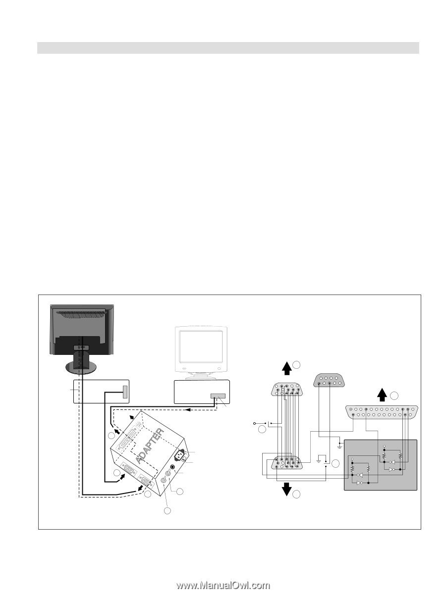
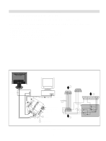
SERVICE OSD 1) Turn off the power switch at the front side of the display. 2) Wait for about 3 seconds and press MENU, POWER switch with 1 second interval. 3) The SVC OSD menu contains additional menus that the User OSD menu as described below. a) MODULE : To select applied module. b) NVRAM INIT : EEPROM initialize(24C08) c) ADC OFFSET : The lowest value of input leves sets to digitally 0(zero). d) ADC GAIN : The highest value of input levels sets to digitally 255. e) ADC CAL : W/B balance sets the gain and offset value. f) ELAPSED CLEAR : To initialize using time. Video Signal Generator Control Line IBM 15 Compatible PC 10 5 Not used RS232C PARALLEL PORT OFF ON 5V F C PARALLEL VGS A MONITOR B V-SYNC ST POWER Power inlet (required) 220 Power Select Switch (110V/220V) Power LED E ST Switch F V-Sync On/Off Switch (Switch must be ON.) A 9 5 11 6 1 6 1 13 25 C 1 14 ON E OFF 5V 4.7K 5V 4.7K 4.7K 74LS06 74LS06 B Figure 1. Cable Connection - 11 -
-
 1
1 -
2
-
3
-
4
-
5
-
6
-
7
-
 8
8 -
 9
9 -
 10
10 -
 11
11 -
 12
12 -
 13
13 -
 14
14 -
 15
15 -
 16
16 -
 17
17 -
 18
18 -
19
-
20
-
21
-
22
-
23
-
24
-
25
-
26
 |
 |