LG LP091HEM Owner's Manual (English) - Page 15
Self-Diagnosis
 |
View all LG LP091HEM manuals
Add to My Manuals
Save this manual to your list of manuals |
Page 15 highlights
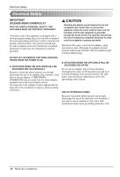
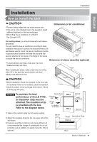
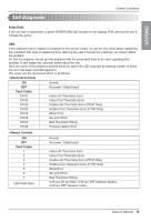
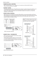
ENGLISH Self-Diagnosis Control Locations FUNCTION: If the unit has a malfunction, a green OPERATION LED located on the Display PCB used by the unit to indicate the errors. USE: If the customer has to register a complaint to the service center, he can be very clear about registering the complaint that what is happening & by referring the user's manual the customer can clearly define the problem. So that the engineer should go fully prepared with the prescribed tools to be used regarding that problem. It also keeps the customer aware about the unit. Here are some of the problems defined below for which the LED indicates by flashing number of times the error has been recorded against it. The errors are the mentioned which is as follows: • Electrical Controls ON Normal OFF No power / failed board Fault Codes CH 01 Indoor Air Thermistor Error CH 02 Indoor Coil Thermistor Error CH 03 Outdoor Air Thermistor Error (PTHP Only) CH 04 Outdoor Coil Thermistor Error (PTHP Only) CH 05 Mode Error CH 06 Set point Error CH 07 Bad Thermistor Wiring CH 09 Pressure Switch Error • Manual Controls ON OFF Fault Codes 1 2 3 4 5 6 7 LED Flash Rate Normal No power / failed board Indoor Air Thermistor Error Indoor Coil Thermistor Error Outdoor Air Thermistor Error (PTHP Only) Outdoor Coil Thermistor Error (PTHP Only) Mode Error Set point Error Bad Thermistor Wiring 0.25 sec On per flash, 0.25 sec OFF between flashes, 2.00 sec OFF between codes. Owner's Manual 15
-
 1
1 -
2
-
3
-
4
-
5
-
6
-
7
-
8
-
9
-
 10
10 -
 11
11 -
 12
12 -
 13
13 -
 14
14 -
 15
15 -
 16
16 -
 17
17 -
 18
18 -
 19
19 -
 20
20 -
21
-
22
-
23
-
24
-
25
-
26
-
27
 |
 |