LG LP120CED1 Owners Manual - Page 18
Remote/local, Control, Energy, Thermostat
 |
View all LG LP120CED1 manuals
Add to My Manuals
Save this manual to your list of manuals |
Page 18 highlights
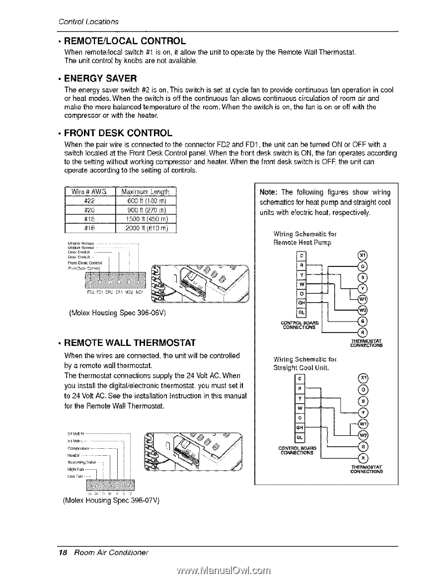
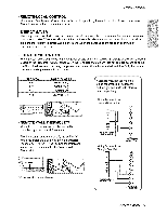
Contro! Locations • REMOTE/LOCAL CONTROL When remote4oca_ switch #1 is on, it _low the unit to o_rate by the Remote W_l Thermos_L The unit contro_ by knobs are net av_l_le • ENERGY SAVER The energy saver switch _ is on This switch is set _ cycle fan to provide continuous _an operation in cool or heat modes When the switch is off _e cointinuous fan allows continuous circulation of room air and make the more ba_anc_ temperature of the room When _e switch is on, the fan is on or off wffh tlhe comlpressor or with the heater , FRONT DESK CONTROL When _e _ir wire is _nnect_ to the connector FD2 and FD!, the unit can _ turned ON or OFF with a switch Io_ted at the Front Desk Contro_ p_neL When _e front desk switch is ON, the fan _erates ac_rding to the setting without working _mpres_r and heater When the front desk sw_ch is OFF the un_ _n operate ac_rding to the setting of control& ....W...i.r.:e# AWG 22 ........... 8 #__ ...._..o..o. _!_tom _02 FDI OR2 b_l _$2 t¢ I Note: The following figures show wiring schematics for heat pump and straight icool units witlh eiec#ic heat re_e_ively. WM#g Schematic f_ ¢ ® ® y w_ (_le,x Housing S_c 396.-06V) • REMOTE WALL THERMOSTAT When the wires are co,nn_ed_ _e unit will be controlled by a remote wail! thermostat, The thermost_: conn_tions supply the 24 Volt AC. When you install the digitalielec#onic therm_, you must set it to 24 Vo_ _,, See the ins_llllation[nstructioin in _is manu_ for the Remote W_I Thermostat. eL CONI_,_S ® THE_iO_I"AT 24 '_N _MO_TAT (Molex Housing Spec 3_07V} 18 Room Air Conditioner
-
 1
1 -
2
-
3
-
4
-
5
-
6
-
7
-
8
-
9
-
10
-
11
-
12
-
 13
13 -
 14
14 -
 15
15 -
 16
16 -
 17
17 -
 18
18 -
 19
19 -
 20
20 -
 21
21 -
 22
22 -
 23
23 -
24
-
25
-
26
-
27
 |
 |