LG LT1010CR Owners Manual - Page 14
Procedure
 |
View all LG LT1010CR manuals
Add to My Manuals
Save this manual to your list of manuals |
Page 14 highlights
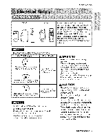
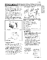
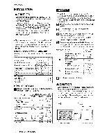
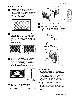
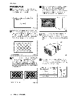
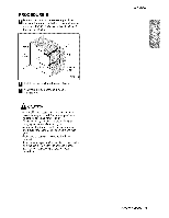
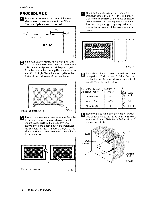
Installation PROCEDURE Bi _ _ired the lieuvers at the back of the wail sleeve to 60 ° angle as. shown in the FIG 9. The use of pliers is re_mmended_ Rear Lo_vers I 7 !,bt D Remove the backing from the Vertical insulation strip, 15%,s x 1_,,_x ! _,'_and attach that to the inside right d the steeve as shown _1_, Remove the backing from the Around Insulation strip 67% x 1_,,_x _ and attach that fo _e inside #ont ,of the sleeve as, shown below. _door Outdoor (Top View) FIG,, '9 lf _e walil sleeve already has a rear gdlle, sMp to step 4. if the walil slieeve does not ha_ a rear F_G. 12 9rilile or Iouvered panel, install the p_astic gdlle from the kit. Cut the plastic grille to 25,°1/2" wide _ emove the, metai rear gri!le and replace it with the plastic rear grille to imDove unit energy and 15o!/4 " high. Place the plastic grille to the effiiciency_ The plastic grille r_uces the amount inside of the wall sleeve at the rear flange. of hot air discha_-ge tihat reciirculates through the unit, Pia_ the plastic griliie FIG. t0 FIG. !3 _ asten the 4 washer sc[ews to s_ure the grille to the waft sleeve, if you need plastic nuts to mount Ipiastic gri[ile to the inside of the wall sleeve, there are plastic nuts in the insta_fation kit. The nuts are insta[f_ from the inside of the sleeve, and arre pieced into the square holes oil the rear flanges. ff the _pth of your existing wall slee_ is less than or equal to 18," skip to step, 7, Otherwise cut the _tfles and the su_ort Mocks according to [e,ngth "A" in the table be_o,w. Depth_D_o' f the exi_ing Length "A" wallsleeve (inches) 3/4 1 3/4 19-_/_
-
 1
1 -
2
-
3
-
4
-
5
-
6
-
7
-
8
-
 9
9 -
 10
10 -
 11
11 -
 12
12 -
 13
13 -
 14
14 -
 15
15 -
 16
16 -
 17
17 -
 18
18 -
 19
19 -
20
-
21
-
22
-
23
 |
 |
