LG LT1010CR Owners Manual - Page 16
Air CoinditJonier
 |
View all LG LT1010CR manuals
Add to My Manuals
Save this manual to your list of manuals |
Page 16 highlights
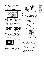
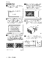
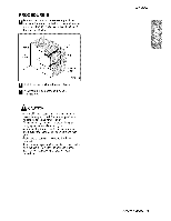
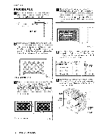
instalia#on PROCEDURE C _ R_iro_ the louvers at the back of the wa_l sleeve to 60 ° angle as, shown in the FIG 16 The u_ of pliers is, r_ommen_d, 7_ Rea_Louvers (Top View) Remove the ba,_ing from the Horizontal _nsulatioin strip 23h:32 x 138 x 13,_ and attach that to the inside right of the sleeve as shown _low. Remove the ba_.ing from the A_ound Ins,ulatioin strip 59_h,_2x: 1% x 1% and attach that t,o the inside front of the slee.te ,as shce_n _low. Indoor Out.or q FIG. 16 lf _e wall sleeve already has a rear gdHe sMp to step 4. if the walil sleeve d_s not have a rear 9rilile or ]ouvered pane], install the plastic gdlle fm,m the kit. Cut the plastic gdlle to 26-1/2" wide and 15o!/2 " high. Place the plastic grille ilo the inside of the-wail sleeve at the rear flange. 8_ HG. t9 [1the _pth of you_ existing sleeve is less than or equal to 18", sk_ to step 7. _ePwise, cu_ the baf|l_ and the support b_oc_ according to Length 'W' in the table _]ow, Oepth_'D'' of the ,existing Length "A° 18
-
 1
1 -
2
-
3
-
4
-
5
-
6
-
7
-
8
-
9
-
10
-
 11
11 -
 12
12 -
 13
13 -
 14
14 -
 15
15 -
 16
16 -
 17
17 -
 18
18 -
 19
19 -
 20
20 -
 21
21 -
22
-
23
 |
 |
