LG LT1030CR Owners Manual - Page 16
Procedure
 |
View all LG LT1030CR manuals
Add to My Manuals
Save this manual to your list of manuals |
Page 16 highlights
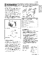
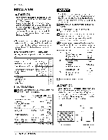
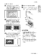
Installation PROCEDURE C _ edirect the. Iieu_re at the back ot the web sleeve to 60 _'angle as s,hewn in the FiG 14 The u_ of pBers is r_ommended_ "t:32 Rea; Louvers (Top View} FIG, 14 ]f the wallll sl_e already has a rear gdlle, skip to step 4. it the wallll slieeJe does not have a rear g_iBe or ]ouvered panel instet] the p]astic grBfe f_o,m the kiL Cat the plastic g[ile to 26.°1/2 ' wide and ! 5o!!2 ' high Piece the plasti,c grille ilo the inside of the waB sJeeve at the rear flank. Remove the backing from tlhe Horizontal Ens,u]atioinstrip 237,_ × 13_sx !_ and attach that to the inside right o1'the s_eve as shown _low: Remove the be_ing from '[he Around _nS;U_:_Oi[_ strip 5927G_ × 1% × 1% and erich that to the insi_ front o{ the s]e_e as shown below: Indoor Out.or q 8v_ _ F_G. 17 if the depth of you_ existing sle_e is less than or equal to 18_', s_p to step 7. OthePwi_, cut |he baftl_ and the suppor[ M_ks according to Len_h 'W' in the table _]ow. 18
-
 1
1 -
2
-
3
-
4
-
5
-
6
-
7
-
8
-
9
-
10
-
 11
11 -
 12
12 -
 13
13 -
 14
14 -
 15
15 -
 16
16 -
 17
17 -
 18
18 -
 19
19 -
 20
20 -
 21
21 -
22
-
23
-
24
-
25
-
26
 |
 |
