LG M2400HR Service Manual - Page 16
Room Air Conditioner, Disassembly - appliances
 |
View all LG M2400HR manuals
Add to My Manuals
Save this manual to your list of manuals |
Page 16 highlights
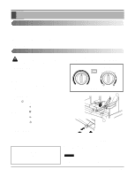
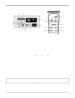
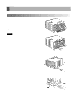
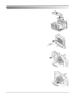
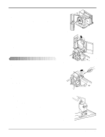
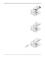
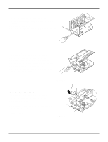
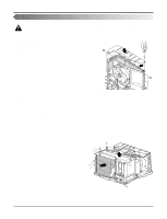
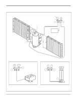
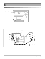
Disassembly 10. CAPACITOR 1. Remove the control box. (Refer to section 3) 2. Remove the screw and knobs which fasten the display panel. 3. Disconnect the 2 leads from the rocker switch and remove the panel. 4. Remove a screw and unfold the control box. (See Fig. 27) 5. Remove the screw and the clamp which fastens the capacitor. (See Fig. 27) 6. Disconnect all the leads of capacitor terminals. 7. Re-install the components by referring to the removal pro- cedure, above. Figure 27 11. POWER CORD 1. Remove the control box. (Refer to section 3) 2. Unfold the control box. (Refer to section 10) 3. Disconnect the grounding screw from the control box. 4. Disconnect 2 receptacles. 5. Remove a screw which fastens the clip cord. 6. Pull the power cord. (See Fig. 28) 7. Re-install the component by referring to the removal pro- cedure, above. (Use only one ground-marked hole for ground connection.) 8. If the supply cord of this appliance is damaged, it must be replaced by the special cord. (The special cord means the cord which has the same specification marked on the supply cord fitted to the unit.) Figure 28 12. THERMOSTAT 1. Remove the control box. (Refer to section 3) 2. Unfold the control box. (Refer to section 10) 3. Remove the 2 screws which fasten the thermostat. 4. Disconnect all the leads of thermostat terminals. 5. Remove the thermostat. (See Fig. 29) 6. Re-install the components by referring to the removal procedure, above. Figure 29 16 Room Air Conditioner
-
 1
1 -
2
-
3
-
4
-
5
-
6
-
7
-
8
-
9
-
10
-
 11
11 -
 12
12 -
 13
13 -
 14
14 -
 15
15 -
 16
16 -
 17
17 -
 18
18 -
 19
19 -
 20
20 -
 21
21 -
22
-
23
-
24
-
25
-
26
-
27
-
28
-
29
-
30
-
31
-
32
-
33
-
34
-
35
-
36
 |
 |
