LG M2404ER Service Manual - Page 6
Disassembly Instructions
 |
View all LG M2404ER manuals
Add to My Manuals
Save this manual to your list of manuals |
Page 6 highlights
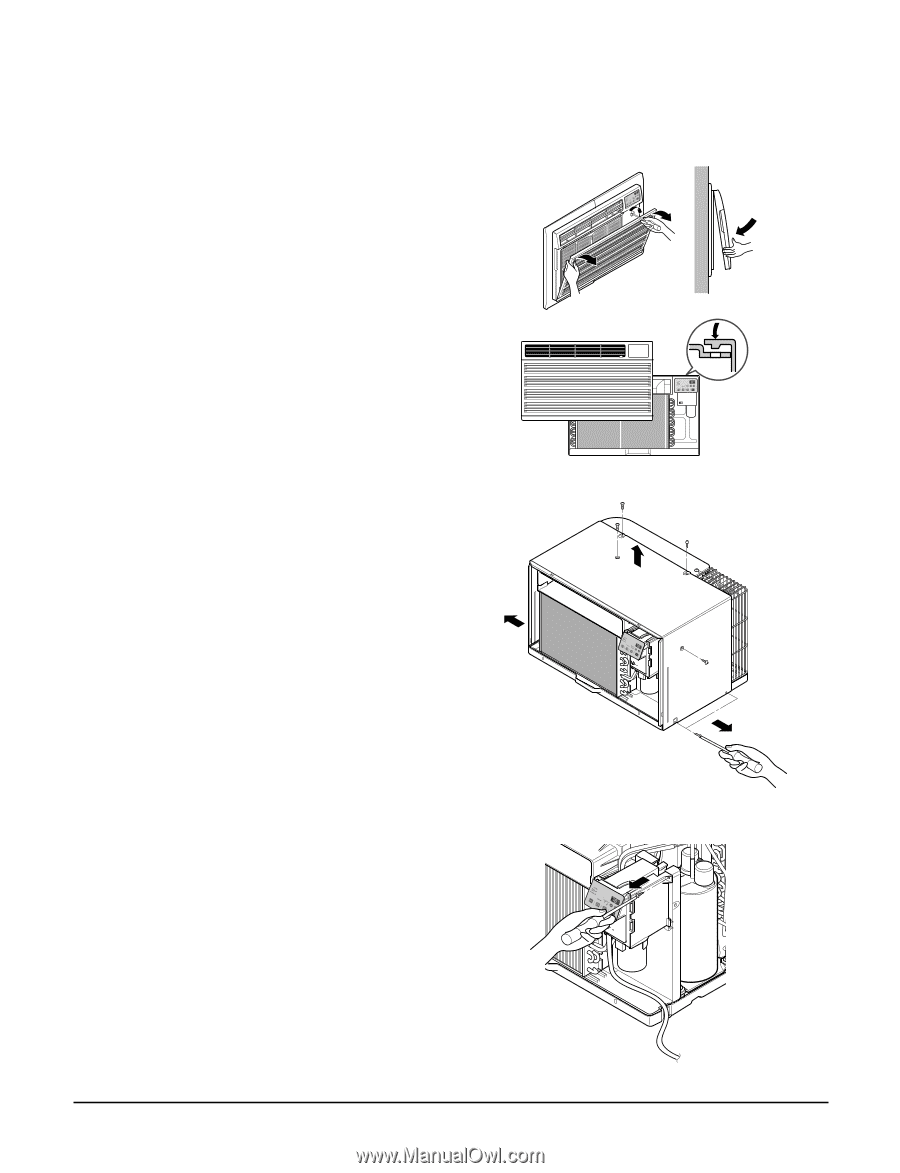
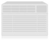
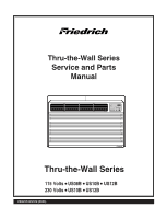
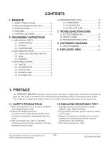
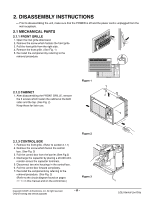
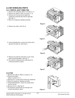
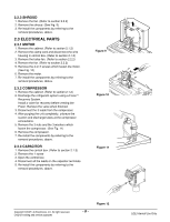
2. DISASSEMBLY INSTRUCTIONS - Prior to disassembling the unit, make sure that the POWER is off and the power cord is unplugged from the wall receptacle. 2.1 MECHANICAL PARTS 2.1.1 FRONT GRILLE 1. Open the inlet grille downward. 2. Remove the screw which fastens the front grille. 3. Pull the front grille from the right side. 4. Remove the front grille. (See Fig. 1) 5. Re-install the component by referring to the removal procedure. 2.1.2 CABINET 1. After disassembling the FRONT GRILLE, remove the 6 screws which fasten the cabinet at the both sides and the top. (See Fig. 2) Keep these for later use. Figure 1 2.1.3 CONTROL BOX 1. Remove the front grille. (Refer to section 2.1.1) 2. Remove the screw which fasten the control box. (See Fig. 3) 3. Pull the control box from the barrier.(See Fig.3) 4. Discharge the capacitor by placing a 20,000 ohm resistor across the capacitor terminals. 5. Disconnect two wire housings in the control box. 6. Pull the control box forward completely. 7. Re-install the components by referring to the removal procedure. (See Fig. 3) (Refer to the circuit diagram found on pages 29~30 in this manual and on the control box.) Figure 2 Figure 3 Copyright ©2007 LG Electronics. Inc. All right reserved. Only for training and service purposes -6- LGE Internal Use Only
-
 1
1 -
 2
2 -
 3
3 -
 4
4 -
 5
5 -
 6
6 -
 7
7 -
 8
8 -
 9
9 -
 10
10 -
 11
11 -
 12
12 -
13
-
14
-
15
-
16
-
17
-
18
-
19
-
20
-
21
-
22
 |
 |